86
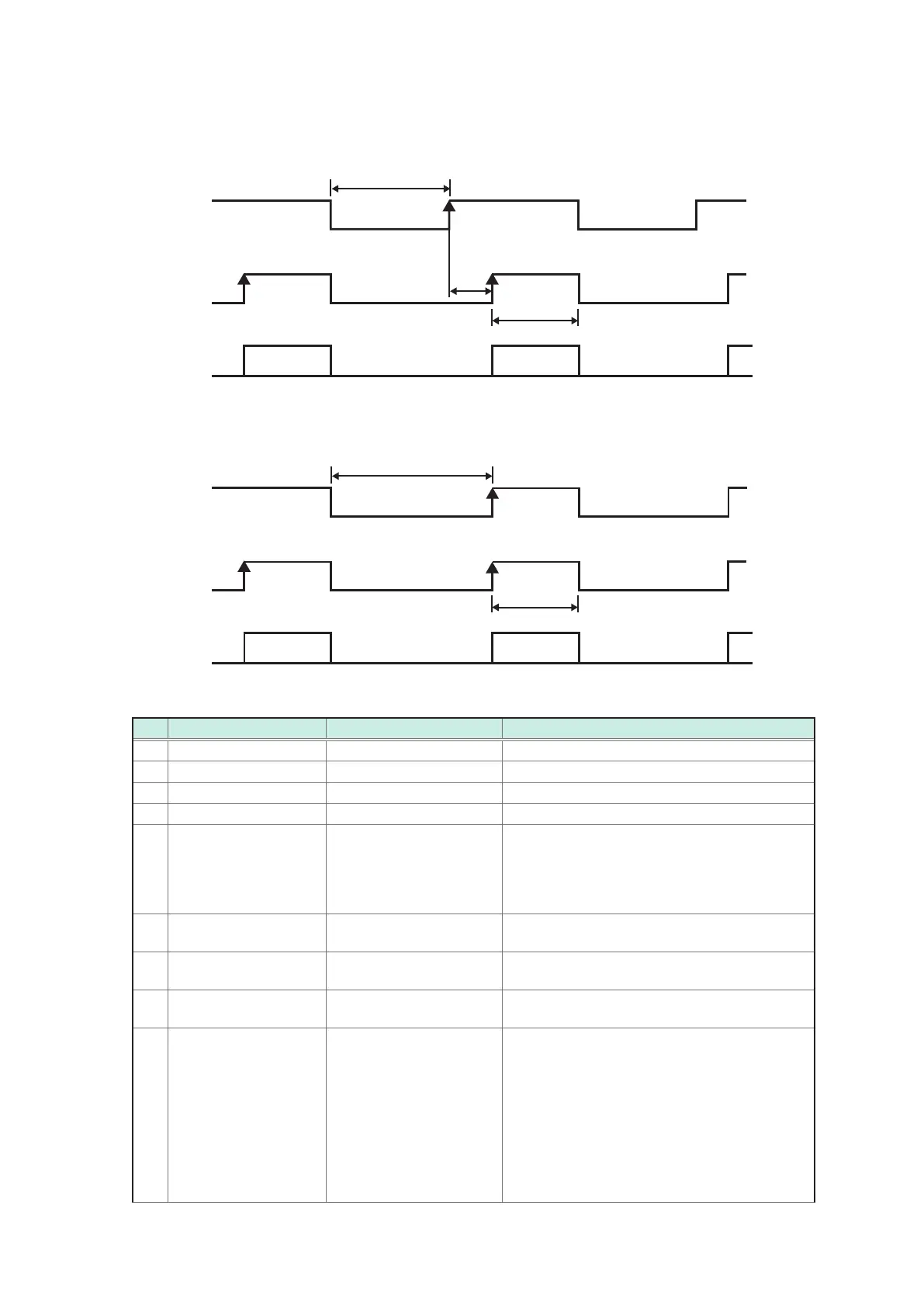
Timing Chart
(2) When the internal trigger [INT] is set
In the case of measurement functions (R, X, V, T), (Z,
θ
, V, T), (R, X, T), (Z,
θ
, T)
INDEX
EOM
Judgment
result
t9
OFF
OFF
ON
ON OFF
OFF
t13
t12
Judgment results: HI, IN, LO, PASS, FAIL, ERR
In the case of measurement functions (V, T)
INDEX
EOM
Judgment
result
OFF
OFF
ON
ON
OFF
OFF
t13
t12
Timing chart interval descriptions
Item
Contents Time (approximately) Remarks
t0 Trigger pulse ON-time 0.1 ms or more
t1 Trigger pulse OFF-time 1 ms or more
t2 Response time 0.1 ms
t3 Contact check time 10 ms
t4 Self-Calibration time 210 ms
When self-calibration is set to AUTO, self-
calibration is performed. In the case of the
MANUAL setting, if the CAL signal is input, self-
calibration is performed. For details, refer to
p. 41.
t5
Voltage measurement
sampling time
100 ms/400 ms/ 1 s Measurement speed: FAST/MED/SLOW
t6
Voltage measurement
calculation time
0.1 ms
t7
Switching time of
measurement circuit
58 ms
t8
Impedance
measurement sampling
time
(1÷f)×N+T+0.016*
f: Measurement frequency, N: measurement
wave number, T: Control time for sampling.
The measurement wave number is determined
by the measurement speed and the average
number. For details, refer to p. 24, p. 42,
and p. 102.
Sampling control time differs due to the frequency.
T=0.088÷ f (f: 0.1 Hz to 66 Hz)
T=0.36÷ f (f: 67 Hz to 250 Hz)
T=1.5÷ f (f: 260 Hz to 1050 Hz)