87
Timing Chart
Item
Contents Time (approximately) Remarks
t9
Calculation time
in impedance
measurement
70 ms
Measurement frequency: 1 kHz, Z measurement
speed: SLOW, Slope correction: representative
value of ON
t10 Sample delay (1÷f)×M* +0.005 s
f: Measurement frequency, M: Sample delay
setting wave number
For the setting wave number, refer to (p. 38).
t11
Measurement signal
zero-cross detection
(1÷f) or less*
f: Measurement frequency
To prevent charging and discharging the
measuring object, the applied AC signal is
processed to end at zero cross. It will be applied
if the measurement signal zero cross stop
function is ON. (p. 47)
t12
EOM pulse width in the
internal trigger
100 ms
t13 Total measurement time
t2+t3×2+t4+t5+t6+t7+t8+t9
+t10+t11
In the case of the functions (Z,
θ
,V,T) or (R,X,V,T)
t2+t3×2+t7+t8+t9+t10+t11 In the case of functions (Z,
θ
,T) or (R,X,T)
t2+t3×2+t4+t5+t6+t7 In the case of the functions (V,T)
* Unit is “s”.
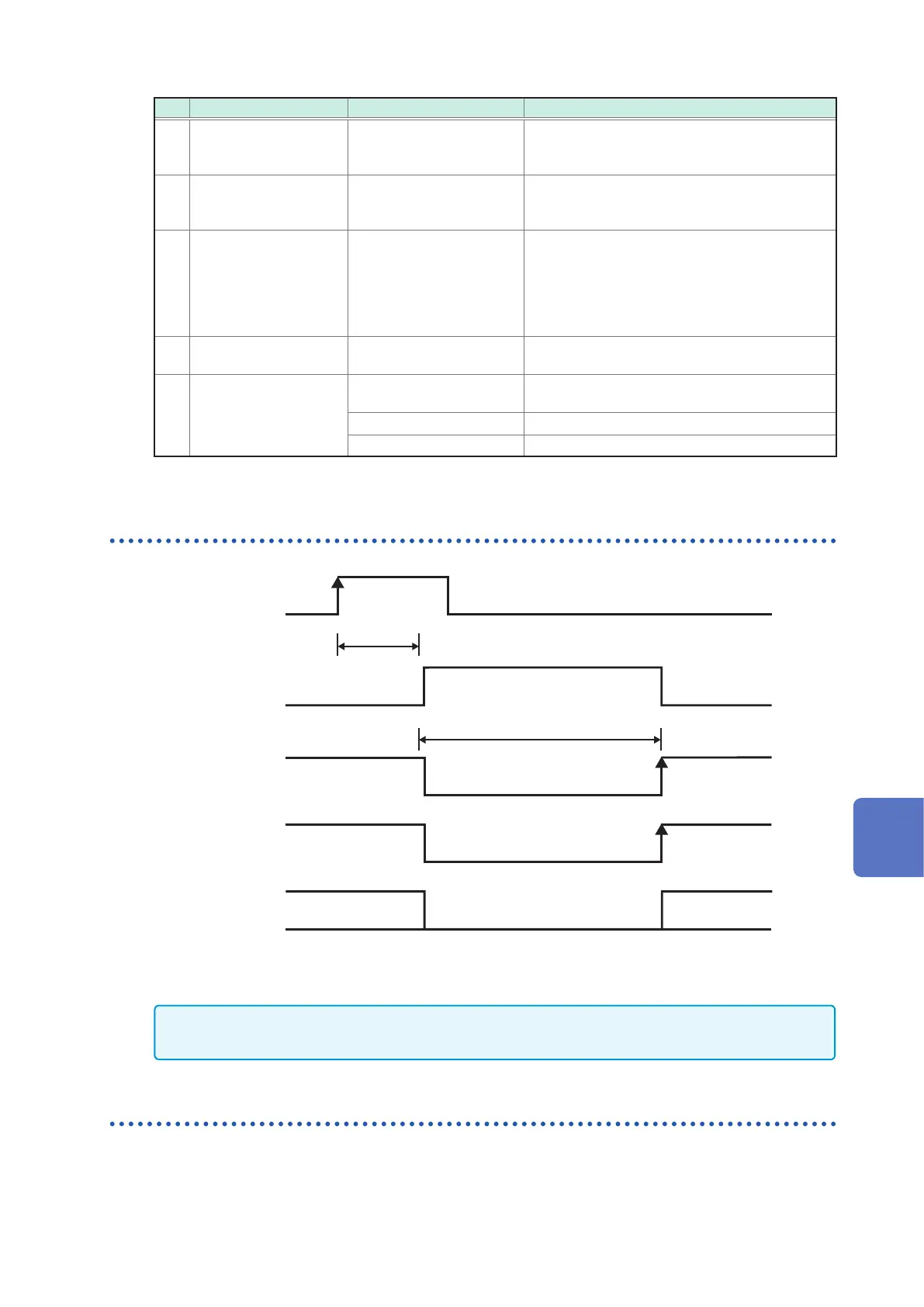
Timing of the zero adjustment
EOM
OFF
OFF
ON
ON
0ADJ_SPOT
or 0ADJ_ALL
Zero adjustment
processing
INDEX
ERR
ON
During zero adjustment
Greater
than 20 ms
The ERR signal becomes ON or OFF dependent on the result of the zero adjustment. When the zero
adjustment is performed normally, the ERR is OFF. When it is not performed normally, the ERR is ON
synchronously with the EOM.
IMPORTANT
For signals 0ADJ_SPOT and 0ADJ_ALL, input when it is not in measurement state.
Timing of the self-calibration
When the self-calibration setting is [AUTO], the self-calibration always is performed before the voltage
measurement. The self-calibration is performed to maintain the accuracy of the voltage calibration. In the case
of the measurement functions (R, X, T) and (Z,
θ
, T) where the voltage measurement is not performed, the
self-calibration is not performed. (Even if the CAL signal is input, the self-calibration is not performed.)
8
External Control (EXT.I/O)