A8
Inuence of the Eddy Current
Appx. 6 Inuence of the Eddy Current
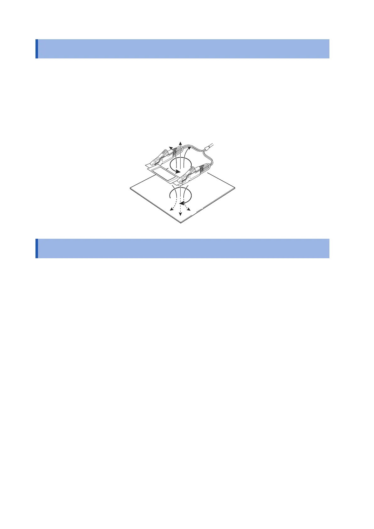
Measurement close to the metal body causes an eddy current to ow due to the dynamic magnetic eld that is
generated by the measurement current of the instrument.
This eddy current generates an inductive voltage with a phase opposite to the measurement current in the
measurement probe. The inductive voltage generated cannot be removed even in the synchronous detection
circuit. Therefore, it may cause a measurement error.
Thus, the measurement instrument using the AC signals needs to take into account the inuence of the eddy
current.
To suppress the inuence of the eddy current, you must not bring the measurement probe without a four-
terminal pair structure close to a metal body.
Appx. 7 Zero Adjustment
Zero adjustment is a function that compensates for the value remaining when a resistance 0
Ω
is measured
and then adjusts the zero-point. Thus, zero adjustment must be carried out under conditions where a
resistance of 0
Ω
is connected. However, It is very difcult and impractical to connect a sample that has a zero
resistance value.
Accordingly, zero adjustment is actually carried out to adjust the zero-point by creating conditions where a
pseudo resistance of 0
Ω
is connected.
To create the conditions where a pseudo resistance of 0
Ω
is connected:
When the ideal resistance of 0
Ω
is connected, from the relational expression of Ohm’s law
E
=
I
×
R
, the
voltage between SENSE-H and SENSE-L becomes 0 V. That is, if the voltage between the SENSE-H and the
SENSE-L is made to be 0 V, the same conditions as when a resistance of 0
Ω
is connected can be created.
When performing zero adjustment with this instrument:
This instrument monitors the condition of the spaces of the four measurement terminals by the measurement
fault detection function. Accordingly, zero adjustment needs to be properly connected to each space of the
terminals. (Figure. Conditions Where a Pseudo Resistance of 0
Ω
is Connected)
First, create a short-circuit between SENSE-H and SENSE-L to cause the voltage between SENSE-H and
SENSE-L to be 0 V. If the wiring resistance of the cable being used
R
SEH
+
R
SEL
is less than several
Ω
, the
resistance of the wiring can be ignored. The explanation is as follows. The SENSE terminals are the voltage
measurement terminals, and thus the current
I
0
is ignored. In the relational expression,
E
=
I
0
×(
R
SEH
+
R
SEL
),
I
0
≈0.
When the resistance of wiring
R
SEH
+
R
SEL
is several
Ω
, the voltage between SENSE-H and SENSE-L becomes
almost zero.
Next, connect the spacing between SOURCE-H and SOURCE-L.
This prevents an error display when the measurement current cannot be own. The wiring resistance of the
cable used
R
SOH
+
R
SOL
must be less than the resistance value with which the measurement current can ow.
In addition, when monitoring the connection condition between SENSE and SOURCE, the spaces between
SENSE and SOURCE must be connected. If the wiring resistance of the cable used
R
Short
is approximately
several
Ω
, the cable is acceptable.
The above wiring makes the measurement current
I
that ows out from SOURCE-H ow into SOURCE-L,
and thus prevents the measurement current that ows out from SOURCE-H from owing into the wiring of
SENSE-H and SENSE-L. Consequently, the voltage between SENSE-H and SENSE-L can be maintained
accurately at 0 V and zero adjustment can be performed.