A19
Calibrating the Instrument
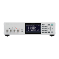
Calibrating voltage measurement
• Use a generator that can output 7 V DC.
• For the connection between this instrument and the generator, refer to Figure illustrated below.
• You must not input the AC current of this instrument to the generator. This may cause a malfunction of the
generator.
• Use the generator with a low output impedance.
• Some of generators may not operate normally.
The instrument
DC generator
SOURCE-H
SENSE-H
SENSE-L
SOURCE-L
Shield
+
-
Figure. Connection to the generator
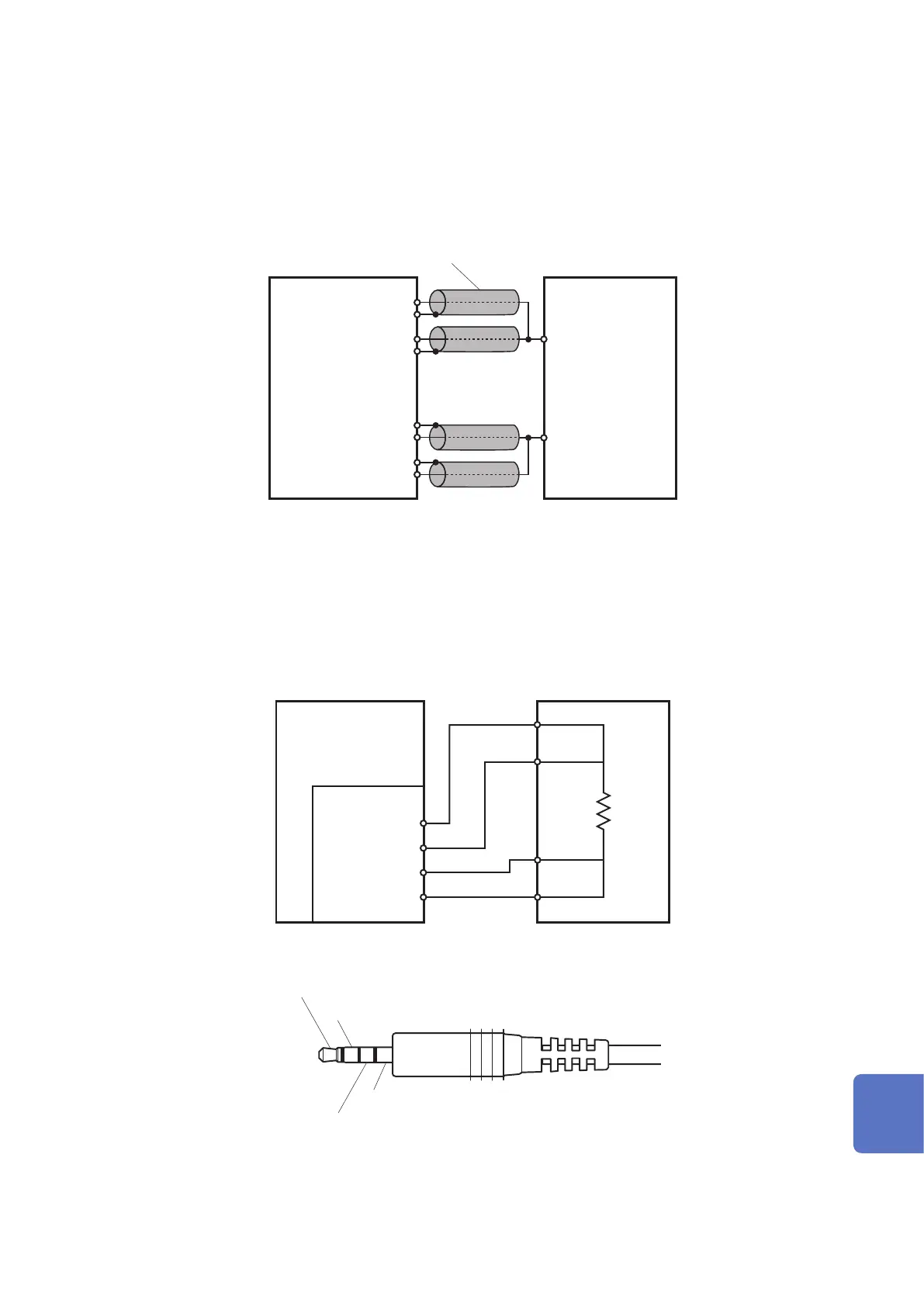
Calibrating temperature measurement
• Calibrate the standard resistor with Pt100 IEC Class A or equivalent.
• For the connection between this instrument and the generator, refer to Figure illustrated below.
• You must use the wiring resistance of both ways less than 10
Ω
.
• Use the connection terminals of
φ
3.5 four-terminal structure (For the four-pole signal cable, refer to Figure
illustrated below.)
Standard resistorThe instrument
TEMP.SENSOR
TEMP C1
TEMP C2
TEMP P1
TEMP P2
Figure. Connecting to the standard resistor
TEMP C1
TEMP C2
TEMP P1
TEMP P2
Figure. Connection terminal’s structure
10
9
8
7
6
5
4
3
2
1
Appx. Ind.
 Loading...