3. C300 Controller Installation and Upgrades
3.2. C300 Controller installation
Series 8 C300 Controller User's Guide
Honeywell
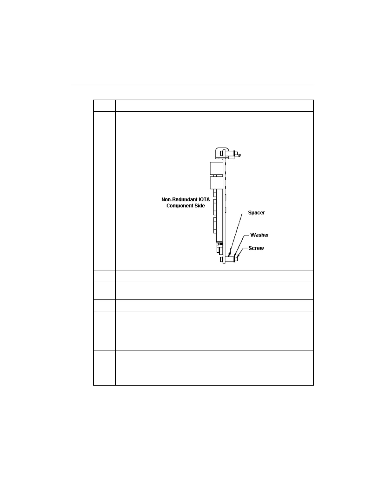
Be sure component side of IOTA is facing up. Refer to the figure below.
Assemble mounting screws, washers and spacers provided. Insert spacers
and washers between backside of IOTA and front of channel.
Position the assembled IOTA board at the proper mounting location.
Thread the four mounting screws only half-way to attach the IOTA board to
the panel. Do not tighten.
Tighten the mounting screws securing the IOTA board to the channel.
Connect FTE-A and FTE-B Ethernet link cables to the RJ-45 connectors on
C300 IOTA board.
The Yellow Cat5 cable connects to the "FTEA" connector on the IOTA.
The Green Cat5 cable connects to the "FTEB" connector on the IOTA.
Connect the Orange Redundancy cable to the REDUNDANCY connector on
the secondary controller IOTA.
Route the cable to the primary controller location and connect it to the
REDUNDANCY connector on the primary controller IOTA.

 Loading...


