4. C300 Controller Configuration
4.6. Convert a redundant C300 Controller to a non-redundant controller
Series 8 C300 Controller User's Guide
Honeywell
The C300 Controller configuration
form closes.
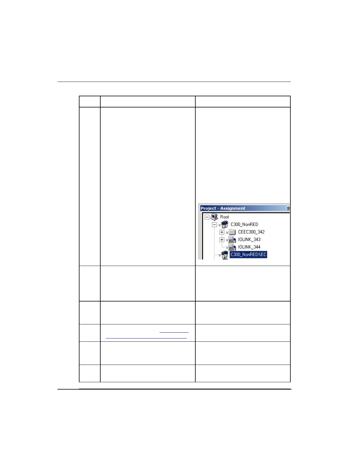
In the Project window:
The C300 Controller icon
indicates that it is configured as
redundant, (showing a double
controller icon). A double 'V'
sign is shown next to the
primary icon.
An additional C300 Controller
icon is created representing the
secondary controller.
Load the primary C300 block to the
controller.
The double 'V' disappears from the
primary C300 icon in the Project
view. The C300 block in the Monitor
view changes from a non-redundant
icon to a redundant icon.
Connect the Redundancy cable
between the redundant controller
pairs.
A 'Not Synchronized' alarm may be
generated.
Perform the procedure To configure
a Secondary C300 Controller block.
Select the Secondary C300
Controller icon. Perform a Load to
the controller.
The double 'V' sign next to the
Secondary C300 icon disappears in
the Project view.
Verify the redundant controller pair
achieves a synchronized state.

 Loading...


