GX-Series Control Panel Installation and Setup Guide
6-84
1 = Internal Telecoms
1 = Int Telecoms
01 = Format
1 = DTMF
1 = Channels 1-16
1 = Output Function
2 = Output Mode
3 = Output Polarity
4 = Diag Recording (not available)
5 = Descriptor (not available)
6 = Lighting (not available)
7 = Output Functions
2 = Acct/Channel
4 = Contact ID
2 = SIA
0 (0-4) 1 = Trigger Events
1 = Status
2 = Groups
2 = Group Settings
1 = Telephone No.
2 = Account No.
3 = Microtech
1 = Trigger Events
1 = Status
2 = Groups
2 = Group Settings
1 = Telephone No.
2 = Account No.
1 = Trigger events
1 = Status
2 = Groups
2 = Ack Timeout
1 = 30 seconds
2 = 60 seconds
3 = Group Settings
1 = Telephone No.
2 = Account No.
1 = Latch
2 = Reflex
3 = Pulse
02 = Telephone No. 1
03 = Account No. 6 digits Max.
04 = Receiver
1 = Single
2 = Dual
3 = Alternate
05 = Telephone No. 2
22 digits Max
22 digits Max
06 = Dial Type
1 = Tone
2 = Pulse
07 = Autotest
1 = Start Time
2 = Intervals
3 = Int. Test
0 - 99 hours
0 = Disabled
1 = Enabled
08 = Engineer Test
09 = No. of Rings
10 (1-20)
10 = Line Fail
1 = Line Volts
0 = Disabled
1 = Enabled
2 = Dial Tone
0 = Disabled
1 = Enabled
3 = Incoming Call
0 = Disabled
1 = Enabled
11 = Fail to Comm
12 = Remote Access
1 = Access Period
1 = Off
2 = All Unset
3 = Any Set
4 = Any Time
2 = Mode
1 = Direct Access
2 = Manager Authorize
3 = Call Back
13 = Call Home
Not Available
14 = Alarm Monitoring
1 = Trigger (1-20)
2 = Telephone No.
3 = Account No.
15 = Backup module
16 = Forced V.21
0 = Disabled
1 = Enabled
17 = SMS Paging
1 = Mobile No.
2 = Centre No.
3 = Format
1 = TAP
2 = UCP (SMS)
3 = UCP (Minicall)
4 = UCP (Numeric)
1 = Status
2 = Groups
4 = Site ID
5 = Password
4 = Group Condition
1 = Off
2 = NOT USED
3 = NOT USED
4 = NOT USED
5 = Ethernet
6 = Int RS232 1
1 = Status
2 = Groups
1 = Status
2 = Groups
1 = Status
2 = Groups
GX-052-V1
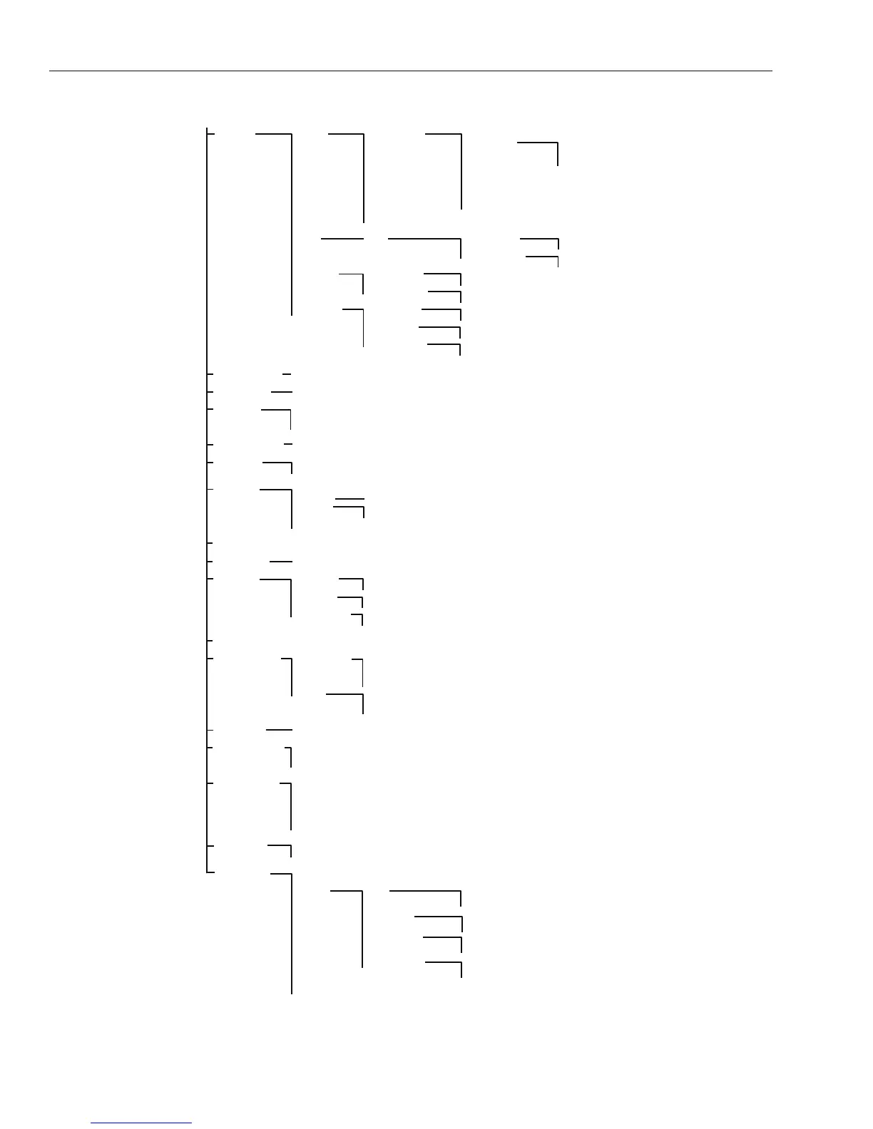
Figure 6-4. Telecom Module Programming Structure
 Loading...


