GX-Series Control Panel Installation and Setup Guide
6-111
5. This displays the battery load test. It is only available for the on-board PSU. Pressing the ent key again
initiates a system wide battery load test. This test is only available for RIO 100 and 101.
6. This displays the AUX1 volts and current draw.
7. This displays the AUX2 volts and current draw.
NOTE: The current reading for the auxilliary supply is the total current of AUX1 and AUX2. The current display
on the keypad for AUX1 or AUX2 is the combined reading of both.
5 = MAX COMMS - the communication level between the GX-Series panel and the MAX/DCM readers.
6 = COMM MODULES - the communication level between the GX-Series panel and the Int Telecoms,
the Int RS232 and Mux Modules.
GX-082-V0
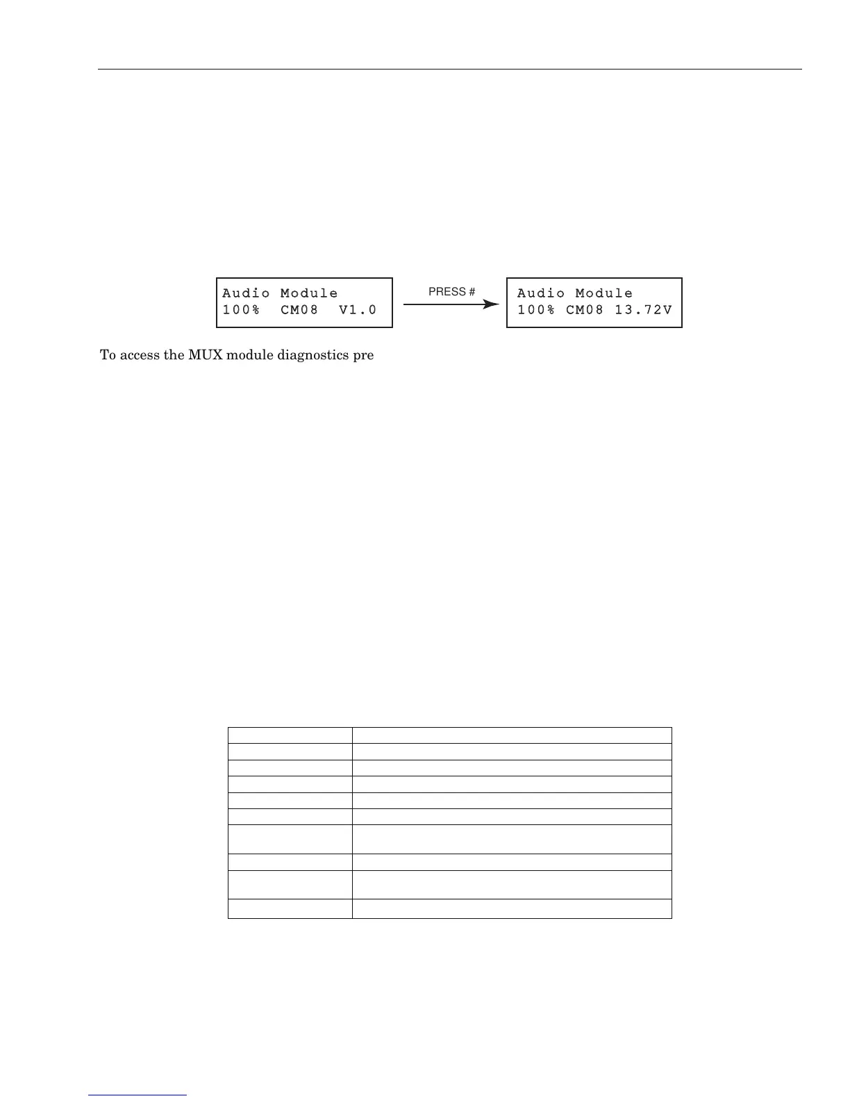
PRESS #
To access the MUX module diagnostics press the asterisk key when the keypad display shows the
diagnostics for the audio interface. Then use the arrow key to scroll between each MUX module. To exit the
menu, to return to the other comms modules diagnostics, press the escape key once.
7 = ZONES - the status of each zone can be viewed.
8 = DCM ZONES - the status of each DCM zone can be viewed.
2 Historical
This option allows a full diagnostic baseline to be performed on the complete GX-Series system, including
power supplies and peripherals. There are 5 selectable options:
1 = View
This option allows any stored baseline data to be viewed from option 61.2.3 = Record.
1. MEMORY TEST - As latest.
2. KEYPAD COMMS - Snapshot value from last test.
3. RIO COMMS - Snapshot value from last test.
4. PSU COMMS - Snapshot value from last test.
5. NOT USED
6. COMM MODULES - Snapshot value from last test.
7. ZONES - Snapshot value from last test. The * key allows printing of results.
8. DCM ZONES - snapshot value from last test.
2 = Timeline
This option shows the time and date when the last check was carried out for each of the areas listed in
table 6-27:
AREA DATA GATHERED
1 = Batt Size Battery size in Ah
2 = Batt RF The battery status of all RF devices. Shows LOW if not ok.
3 = PSU Volts The voltage level of the on-board PSU's
4 = RIO Volts The voltage level of the on-board RIOs
5 = Zone Ohms The current resistance across all zones on the system.
6 = Communication
Type of device, address, and the% level with all peripherals
on the system
7 = Panel memory A check of the panel memory
8 = Total amps
the total current draw for the on-board PSU. This included
aux current and battery current
9 = Batt Volts Voltage level of the battery connected to the control panel
Table 6-27. Historical Timeline
3 = Record
This option initiates a baseline check of areas 1 to 7 in the table above. The display prompts the user to
press the * key to continue with the diagnostic check.
 Loading...


