GX-Series Control Panel Installation and Setup Guide
2-10
1. The maximum number of devices on each line is shown in Table 2-5:
GX-48 (Line 1 only) GX-520 (Lines 1-4)
Keypads
8 8 per line
Touch Center
1 1 per line
RIO's
4
DCM
4 8 per line
RS232
1 1 (line 1 only)
Telecoms
1 1 (line 1 only)
Printer
1 1 (line 1 only)
Ethernet
1 1 (line 1 only)
Table 2-4. Communication Devices
2. Minimum wire gauge for field wiring circuits is 22AWG.
3. The system must be wired in a daisy-chain configuration. Spur and star configurations must not be
used as they reduce the immunity to electrical interference.
4. The cable used must screened twisted pair (Part No W002) to connect the RS485 (AB) line. This would
be CAT5 or Belden 8723 equivalent.
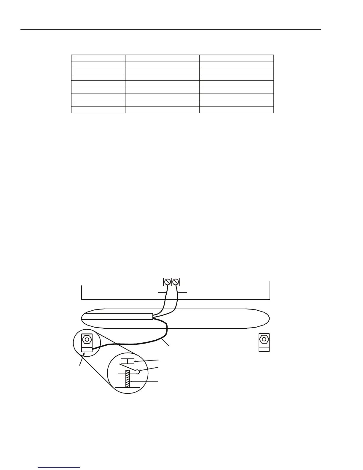
5. Shielded twisted pair cable, where used, is connected to the cabinet ground rod on the GX-Series control
panel using the P-clip and nut supplied (refer to Figure 2-10).
6. The RS485 (AB) line must have a 680 • resistor installed across the A and B terminals of the last
module on the line. If twin lines are connected, both ends must be terminated with 680 • resistors and
the appropriate link on the control panel PCB must be removed (refer to Figure 2-9).
7. There must only be a single AB pair of wires in each of the cables.
8. Supply voltage to the devices is 12 VDC.
9. The power supply in the GX-Series control panel and remote power supplies must not be connected in parallel.
10. The 0 V of all remote power supplies should be connected in common to the 0 V of the GX-Series control
panel.
11. Ensure that any extension loudspeakers are not wired in the same cable as an AB pair of wires.
12. Where possible, ensure that the AB cable is at least 30cm away from any other cables.
13. Where possible, ensure that the AB cable does not run parallel to other cables for extended distances
(maximum 5 meters).
A
B
AB connectors
RS 485 cable
data line
data line
P-clip
Cable screen
Nut
P-clip
Ground Rod
(threaded)
GX-010-V1
Figure 2-10. Connection of cable screen using P-Clip
 Loading...


