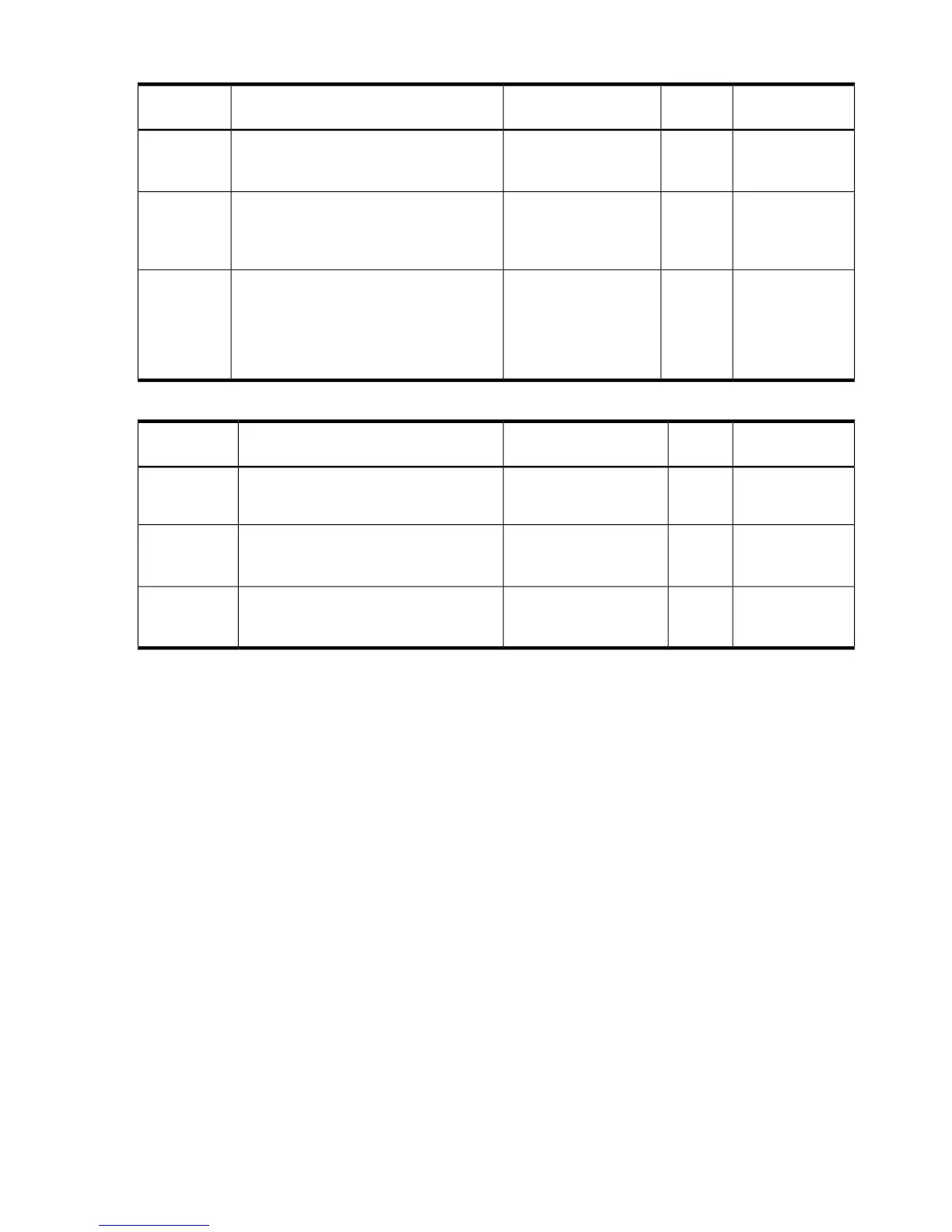
Table 37 Memory subsystem events that light SID LEDs
NotesSourceCauseSample IPMI EventsDiagnostic
LEDs
Light all DIMM
LEDs in rank 0 of
cell 0
SFWNo DIMMs installed (in
rank 0 of cell 0)
Type E0h, 208d:04d
MEM_NO_DIMMS_INSTALLED
DIMMs
Either EEPROM is
misprogrammed or
this DIMM is
incompatible
SFWA DIMM has a serial
presence detect (SPD)
EEPROM with a bad
checksum
Type E0h, 172d:04d
MEM_DIMM_SPD_CHECKSUM
DIMMs
Memory rank is
about to fail or
environmental
conditions are
causing more
errors than usual
WIN
Agent
This memory rank is
correcting too many
single-bit errors
Type E0h, 4652d:26d
WIN_AGT_PREDICT_MEM_FAIL
DIMMs
Table 38 Memory subsystem events that may light SID LEDs
NotesSourceCauseSample IPMI EventsDiagnostic
LEDs
The failing DIMM
rank is deallocated
SFWDetected that an SDRAM
is failing on the DIMM
Type E0h, 4000d:26d
MEM_CHIPSPARE_DEALLOC_RANK
DIMMs
SFWDIMM type is not
compatible with current
DIMMs for this platform
Type E0h, 174d:26d
MEM_DIMM_TYPE_INCOMPATIBLE
DIMMs
SFWDetected a fatal error in
DIMM serial presence
detect (SPD)
Type E0h, 173d:26d
MEM_DIMM_SPD_FATAL
DIMMs
Troubleshooting the power subsystem
The two power supply CRUs for the server provides N+1 redundancy for the server. Each power
supply CRU is identified by the server as 1 and 2 for logging purposes. There are corresponding
LEDs on the diagnostic LED panel for the power supplies.
Power supply CRU failures are identified visually by a single green LED that is turned off when one
or both of the power supplies fail; logged as an IPMI event by voltage sensor logic; and identified
as a power supply CRU failure by iLO3 turning on the appropriate LEDs on the front LED panel.
Power subsystem behavior
For the server, each bulk power supply CRU provides 800 watts of dc power from a nominal 120
VAC, 50-60 Hz; and 1200 watts from a nominal 240 VAC, 50-60 Hz. The BMC chip located on
the system board controls the flow of +12 V dc power to the server CRUs. You can control and
display power supply status remotely with the iLO 3 MP pc and ps commands, respectively.
Typical power up sequence of the server is as follows:
• Power LED on front panel glows steady amber when one or two bulk power supplies are
plugged into nominal ac voltage and the +3.3 VDC housekeeping voltage comes on and
stays on whenever ac power is present.
• The iLO 3, Flash memory, and server intrusion circuits are reset after the +3.3 V dc
housekeeping voltage stabilizes.
• iLO3 monitors the power button on the front panel.
• When the power button is pressed, iLO3 signals the bulk power supplies to fully power up.
88 Troubleshooting