116
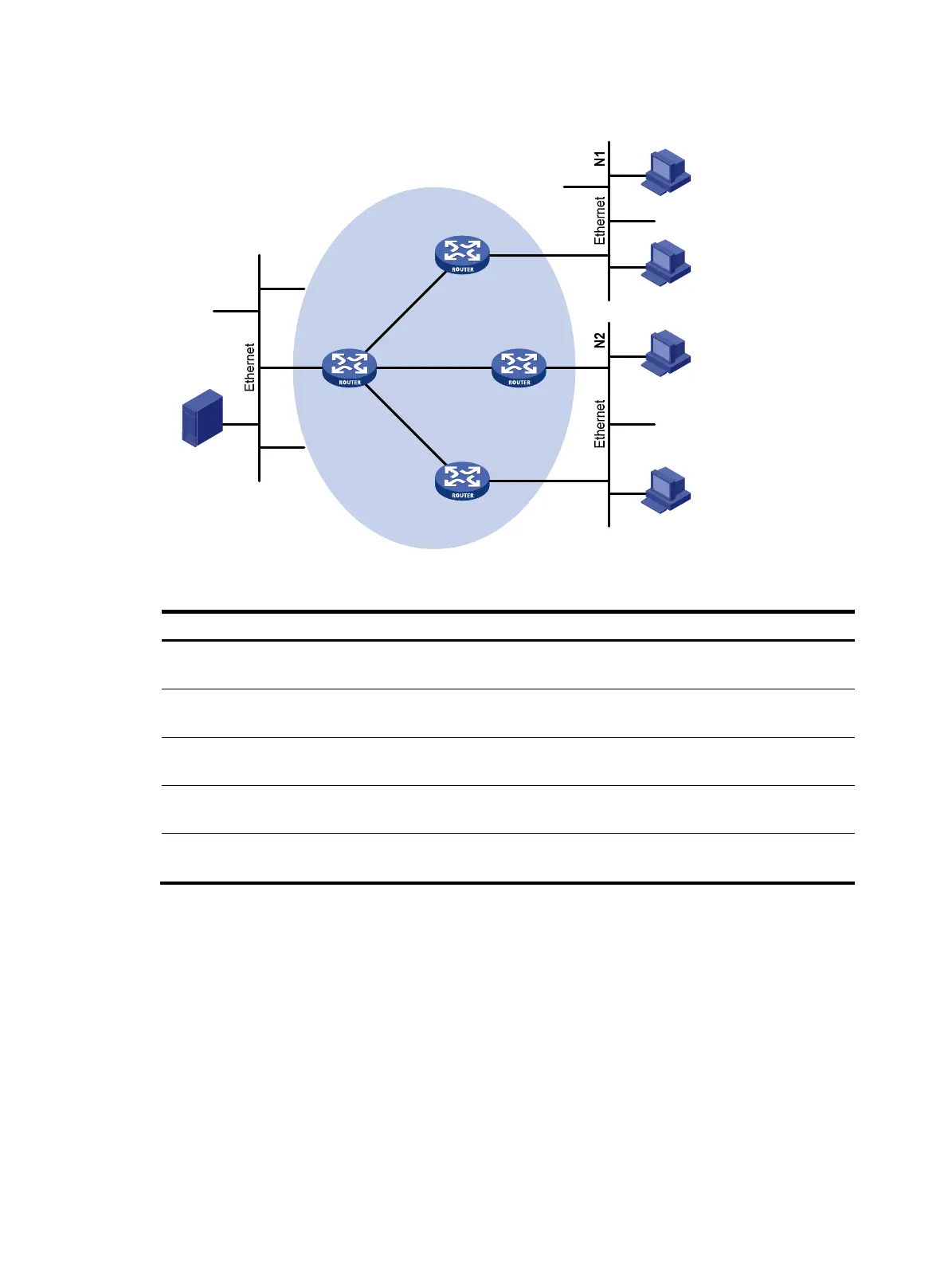
Figure 43 Network diagram
Table 7 Interface and IP address assignment
Device Interface IP address
Device
Interface
IP address
Router A
GigabitEthernet
2/1/1
10.110.1.1/24 Router C
GigabitEthernet
2/1/2
192.168.3.1/24
Router A
GigabitEthernet
2/1/2
192.168.1.1/24
Router D
GigabitEthernet
2/1/1
10.110.5.1/24
Router B
GigabitEthernet
2/1/1
10.110.2.1/24 Router D
GigabitEthernet
2/1/2
192.168.1.2/24
Router B
GigabitEthernet
2/1/2
192.168.2.1/24
Router D
GigabitEthernet
2/1/3
192.168.2.2/24
Router C
GigabitEthernet
2/1/1
10.110.2.2/24 Router D
GigabitEthernet
2/1/4
192.168.3.2/24
Configuration procedure
1. Assign an IP address and subnet mask to each interface according to Figure 43. (Details not
shown.)
2. Configure OSPF on the routers in the PIM-DM domain to make sure the following conditions are
met: (Details not shown.)
{ The routers are interoperable at the network layer.
{ The routers can dynamically update their routing information.
3. Enable IP multicast routing, IGMP, and PIM-DM:
# On Router A, enable IP multicast routing.
<RouterA> system-view
[RouterA] multicast routing
Source
10.110.5.100/24
PIM-DM
Router A
Router B
Router C
Router D
Receiver
Host A
Host B
Host C
Host D
Receiver
GE2/1/1
GE2/1/1
GE2/1/1
GE2/1/1 GE2/1/3 GE2/1/2
GE2/1/2GE
2
/1/4
GE2/1/2
G
E2/
1/2