Portable PLUS Computer
PORTABLE
PLUS
oscilloscope
r o
utines:
fl:
RS-232
oscilloscope
routine
f2:
HP-IL
oscilloscope
routine
f3:
Internal
ROM
read
oscilloscope
routine
f4:
Internal
RAM
write
oscilloscope
routine
f5:
Internal
RAM
read
oscilloscope
routine
f6:
Plug-in
ROM
read
oscilloscope
routine
f7:
Plug-in
RAM
write
oscilloscope
routine
f B:
Plug-in
RAM
read
oscilloscope
routine
Shift
Shift
Shift
Shift
Shif
t
Shif
t
Shif
t
Shift
fl:
f2:
f3:
f4:
f5:
f6:
f7:
f8
:
LCD
RAM
write
oscilloscope
routine
LCD
RAM
read
oscilloscope
routine
Find
Plug-in
RAM
oscilloscope
routine
Find
Plug-in
ROM
oscilloscope
routine
CONFIG
ROM
read
oscilloscope
routine
Find
Modem
oscilloscope
routine
Ex
it
Troubleshooting
8-35
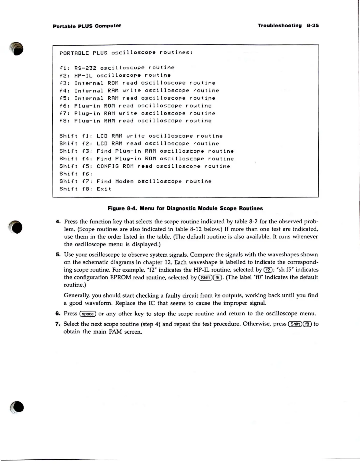
Figure
8-4.
Menu
for
Diagnostic Module
Scope
Routines
4.
Press the function key that selects
the
scope routine indicated by table 8-2 for
the
observed
prob-
lem. (Scope routines are also indicated in table 8-12 below.)
If
more
than
one
test are indicated,
use
them
in
the
order
listed in
the
table. (The default routine
is
also available.
It
runs
whenever
the
oscilloscope
menu
is
di
splayed.)
5.
Use your oscilloscope to observe system Signals.
Compare
the
signals with the
waveshapes
shown
on
the
schematic diagrams in
chapter
12. Each
waveshape
is
labelled to indicate
the
correspond-
ing scope routine. For example, "f2" indicates
the
HP-IL routine, selected
by
@;
"sh
fS"
indicates
the
configuration EPROM
read
routine, selected
by
(Shift
)@
. (The label
"[0"
indicates
the
default
routine.)
Generally, you
should
start
checking a faulty circuit from its
outputs
, working back
until
you find
a good
waveform
. Replace
the
IC
that
seems to cause the improper signa\.
6.
Press
~
or
any
other
key to
stop
the
scope
routine
and
return
to
the
oscilloscope
menu.
7.
Select the next scope
routine
(step 4)
and
repeat
the
test procedure. Otherwise, press
(Shift
)@
to
obtain
the
main
PAM screen.