5-2
Functional
Description
Portable
PLUS
Computer
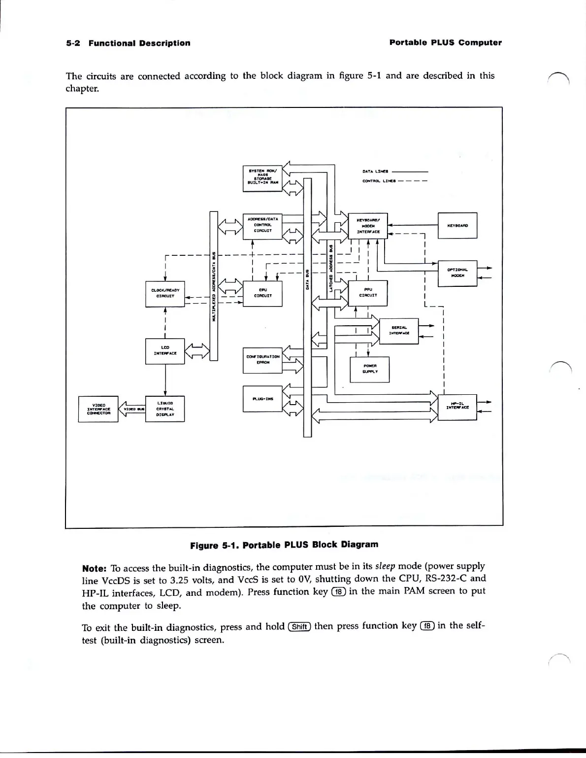
The circuits are connected according to the block diagram in figure 5-1
and
are described in this
chapter.
,----
I
DATA
I..
:
U«I
___
_
Figure 5-1. Portable PLUS Block Diagram
Note:
To
access the built-in diagnostics, the computer must
be
in its
sleep
mode
(power supply
line
VccDS is set to 3.25 volts,
and
VccS is set to
OV,
shutting
down
the
CPU, RS-232-C
and
HP-IL interfaces, LCD,
and
modem). Press function key
00
in the main PAM screen to
put
the computer to sleep.
To
exit
the
built-in diagnostics, press
and
hold (
Shift)
then
press function key
00
in
the
self-
test (built-in diagnostics) screen.