Portable
PLUS
Computer
Troubleshooting
8-9
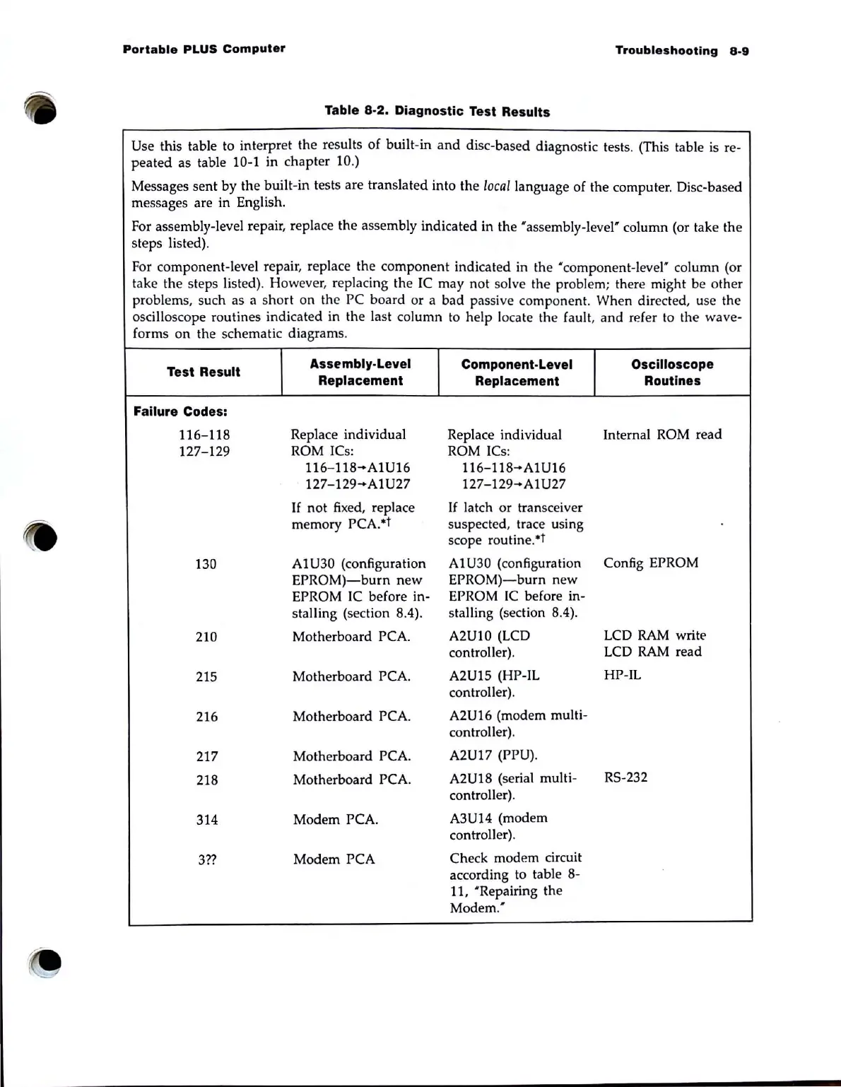
Table 8-2. Diagnostic Test Results
Use this table to interpret the results
of
built-in
and
disc-based diagnostic tests. (This table is re-
peated
as table 10-1 in chapter 10.)
Messages sent by the built-in tests are translated into the /oea/language of the computer. Disc-based
messages are in English.
For assembly-level repair, replace the assembly indicated in the 'assembly-level' column (or take the
steps listed).
For component-level repair, replace the component indicated in the ' component-level' column (or
take the steps listed).
How
ever, replacing the
IC
may not solve the problem; there might be other
problems. such as a short on the PC board or a bad passive component. When directed, use the
oscilloscope routines indicated in the last column to help locate the fault. and refer to the wave-
forms
on
the schematic diagrams.
Test Result
Assembly-Level
Component-Level Oscilloscope
Replacement
Replacement
Routines
Failure Codes:
116-118
Replace individual
Replace individual Internal ROM read
127-129
ROM ICs: ROM ICs:
116-118-A1U16
116-118-A1U16
127-129-A1U27
127-129-A1U27
If
not fixed, replace
If
la
tch
or
transceiver
memory PCA.*t
suspected. trace using
scope routine.*t
130
AIU30 (configuration
Al
U30
(configuration
Config EPROM
EPROM)-burn
new
EPROM)-burn
new
EPROM
IC
before in-
EPROM
IC
before in-
stalling (section 8.4).
stalling (section 8.4).
210
Motherboard PCA.
A2UI0 (LCD
LCD
RAM
write
controller).
LCD
RAM
read
215
Motherboard PCA.
A2U15 (HP-IL
HP-IL
controller).
216
Motherboard PCA.
A2U16 (modem multi-
controller).
217
Motherboard PCA.
A2U17 (PPU).
218
Motherboard PCA.
A2U18 (serial multi-
RS-232
controller).
314
Modem PCA.
A3U14 (modem
controller).
3??
Modem PCA
Check modem circuit
according to table 8-
11, 'Repairing the
Modem.'