8-32
Troubleshooting
Portable
PLUS
Computer
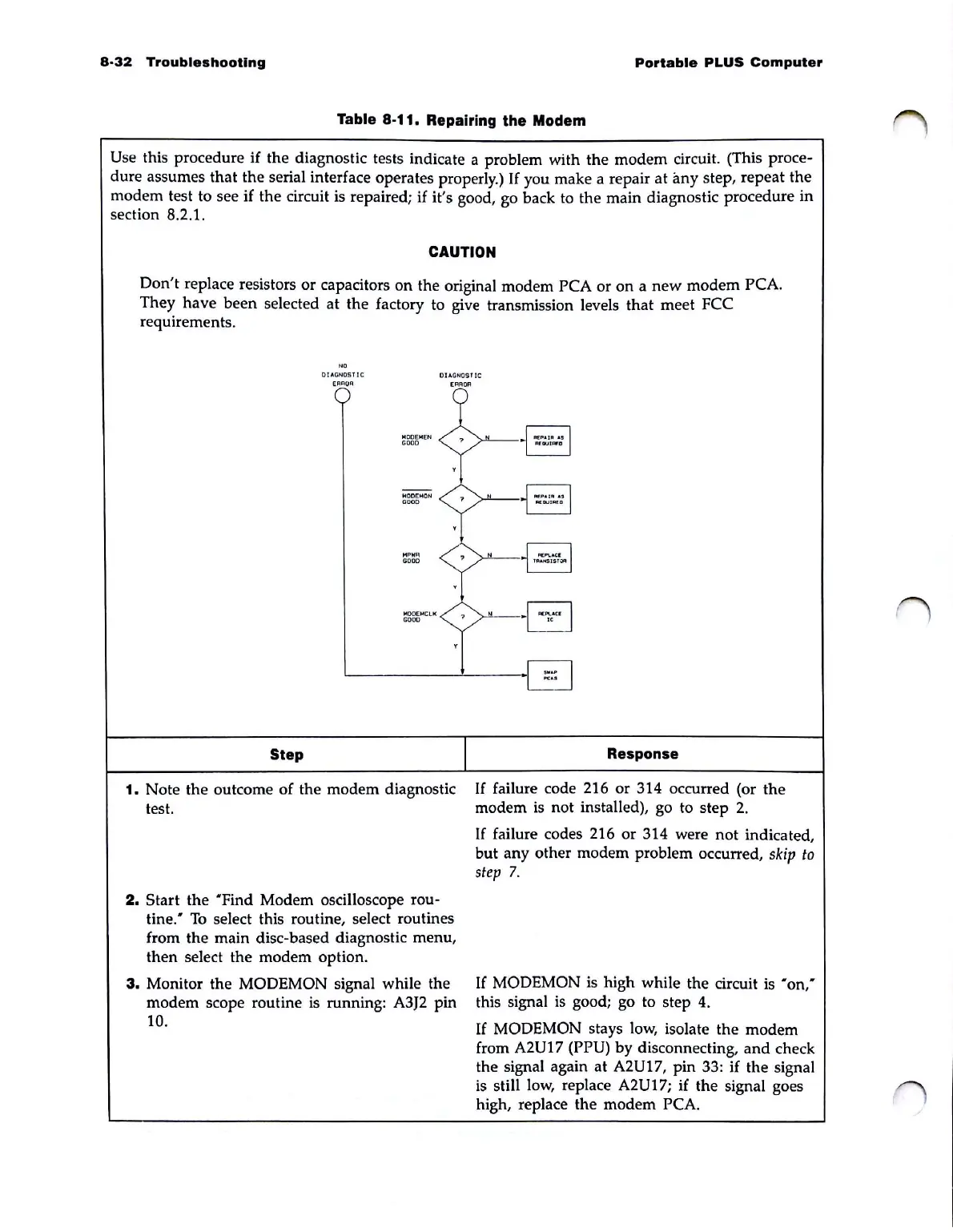
Table 8-11. Repairing the Modem
Use this procedure if the diagnostic tests indicate a problem with the modem circuit. (This proce-
dure assumes that the serial interface operates properly.)
If
you make a repair
at
any step, repeat the
modem test to see
if
the circuit is repaired;
if
it's good, go back
to
the main diagnostic procedure in
section 8.2.1.
CAUTION
Don't
replace resistors or capacitors on the original modem PCA
or
on a
new
modem
PCA.
They
have
been
selected at the factory to give transmission levels that meet FCC
requirements.
"'
01o\ON051
Ie
DIAGNOSTIC
[RROR
[RROR
I'IOO[I'I[N
GOOD
,
--
toIODEI'ION
GOOD
,
",
P
HIl
GOOD
Step
1.
Note the outcome of the modem diagnostic
test.
2.
Start the "Find Modem oscilloscope rou-
tine:
To
select this routine, select routines
from the main disc-based diagnostic menu,
then select the modem option.
3.
Monitor the MODEMON signal while the
modem scope routine
is
running: A3J2 pin
10.
?
?
?
I
§
AfGUIAfa
§
N:1aJ1OII'1l
N
F>t:PI..
.
cr
'''''''''IST;;w:I
Response
If
failure code 216 or 314 occurred (or the
modem
is
not installed), go to step
2.
If
failure codes 216 or 314 were not indicated,
but any other modem problem occurred,
skip
to
step
7.
If
MODEMON
is
high while the circuit
is
"on"
this signal
is
good; go to step
4.
If
MODEMON stays low, isolate the modem
from
A2U17 (PPU) by disconnecting,
and
check
the signal again
at
A2U17, pin 33: if the signal
is
still low, replace A2U17; if the signal goes
high, replace the modem
PCA.