Portable
PLUS
Computer
Troubleshooting
8-33
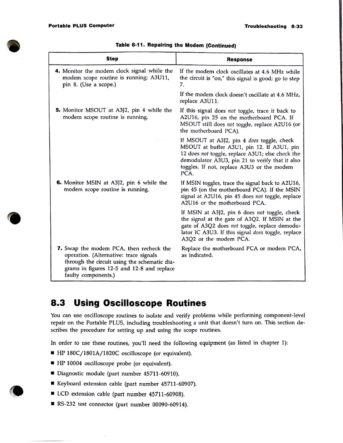
Table 8-11. Repairing the Modem (Continued)
Step
4.
Monitor the
modem
clock signal while the
modem
scope routine is running: A3U11,
pin
8. (Use a scope.)
5.
Monitor MSOUT
at
A3J2, pin 4 while the
modem
scope routine is
running
.
6.
Monitor MSIN at A3J2,
pin
6 while the
modem
scope routine
is
running.
1
7.
Swap
the modem PCA,
then
recheck the
operation. (Alternative: trace signals
through the circuit using
the
schematic dia-
grams
in
figures 12-5
and
12-8
and
replace
faulty components.)
Response
If
the
modem
clock oscillates
at
4.6 MHz while
the circuit is
•
on:
this signal
is
good; go to
step
7.
If
the modem clock doesn't oscillate
at
4.6 MHz,
replace
A3U11.
If this signal does /lot toggle, trace
it
back to
A2U16, pin 25 on the motherboard PCA.
If
MSOUT still does
not
toggle, replace A2U16 (or
the motherboard
PCA).
If
MSOUT
at
A3J2, pin 4
does
toggle, check
MSOUT at buffer A3U1 , pin 12.
If
A3U1, pin
12 does
/lot toggle, replace A3U1; else check
the
demodulator A3U3, pin
21
to verify
that
it also
toggles.
If
not, replace A3U3 or the modem
PCA.
If
MSIN toggles, trace the signal back to A2U16,
pin
45
(on the motherboard PCA).
If
the MSIN
signal at
A2U16, pin
45
does
not
toggle, replace
A2U16 or the motherboard PCA.
If MSIN at A3J2, pin 6 does
not
toggle, check
the signal at the gate of A3Q2.
If
MSIN at
the
gate of A3Q2 does
/lot
toggle, replace
demodu-
lator
IC
A3U3.
If
this signal
does
toggle, replace
A3Q2 or the modem
PCA.
Replace the motherboard PCA or modem PCA,
as indicated.
8.3
Using Oscilloscope Routines
You
can use osciIIoscope routines to isolate
and
verify problems while performing component-level
repair
on
the Portable PLUS, including troubleshooting a unit
that
doesn't
turn
on
. This section
de-
scribes
the
procedure for setting
up
and
using the scope routines.
In order to use these routines, you'll
need
the
following equipment (as listed in chapter 1):
•
HP
180C/1801A/1820C
osciIIoscope (or equivalent).
•
HP
10004 osciIIoscope probe (or equivalent).
• Diagnostic module (part
number
45711-60910).
• Keyboard extension cable
(part
number
45711-60907).
•
LCD extension cable (part
number
45711-60908).
•
RS
-232 test connector (part
number
00090-60914).