Portable PLUS Computer Functional Description 5·7
5.9
HP-IL
Interface
A
1LB3
(A2U15) is used for the HP-IL interface
and
uses the high byte of the internal data bus. Its 2-
MHz clock (supplied
by
the clock/ready circuit to TSCLK*, pin 22) is running
when
the computer is
awake. The interface is powered
on
when
the computer is awake, powered
down
in
the
sleep mode,
and
in
its reset state as the computer wakes up.
Note: The oscillator disable bit
(I/O
address 002F bit
0)
can
be
used to reduce power con-
sumption
when
the
HP
-
IL
loop isn't being used.
HP-IL protocol is described
in
The
HP-IL
Interface
Specification
(HP
part
number
82166-90017)
and
in
The
HP-IL
Integrated
Circuit
User's
Manual
(HP
part
number
82166-90016).
The HP-IL interface connects to external HP-IL devices via connector A2J6. (Refer to the schematic
diagram in figure 12-5 for connector pin assignments.)
5.10
Serial
(RS-232-C)
Interface
The serial interface (figure 12-5, center) is compatible with RS-232-C
and
CCITT
V.24
and
V.28
speci-
fications. The serial interface performs the following functions:
• Links the mainframe
and
the serial port.
• Provides
part
of
the link between the mainframe
and
the modem circuits.
The computer is configured as a data terminal equipment device
at
the serial interface connector A2J7
(nine-pin female subminiature D). The connector pin assignments are
shown
in table 5-1.
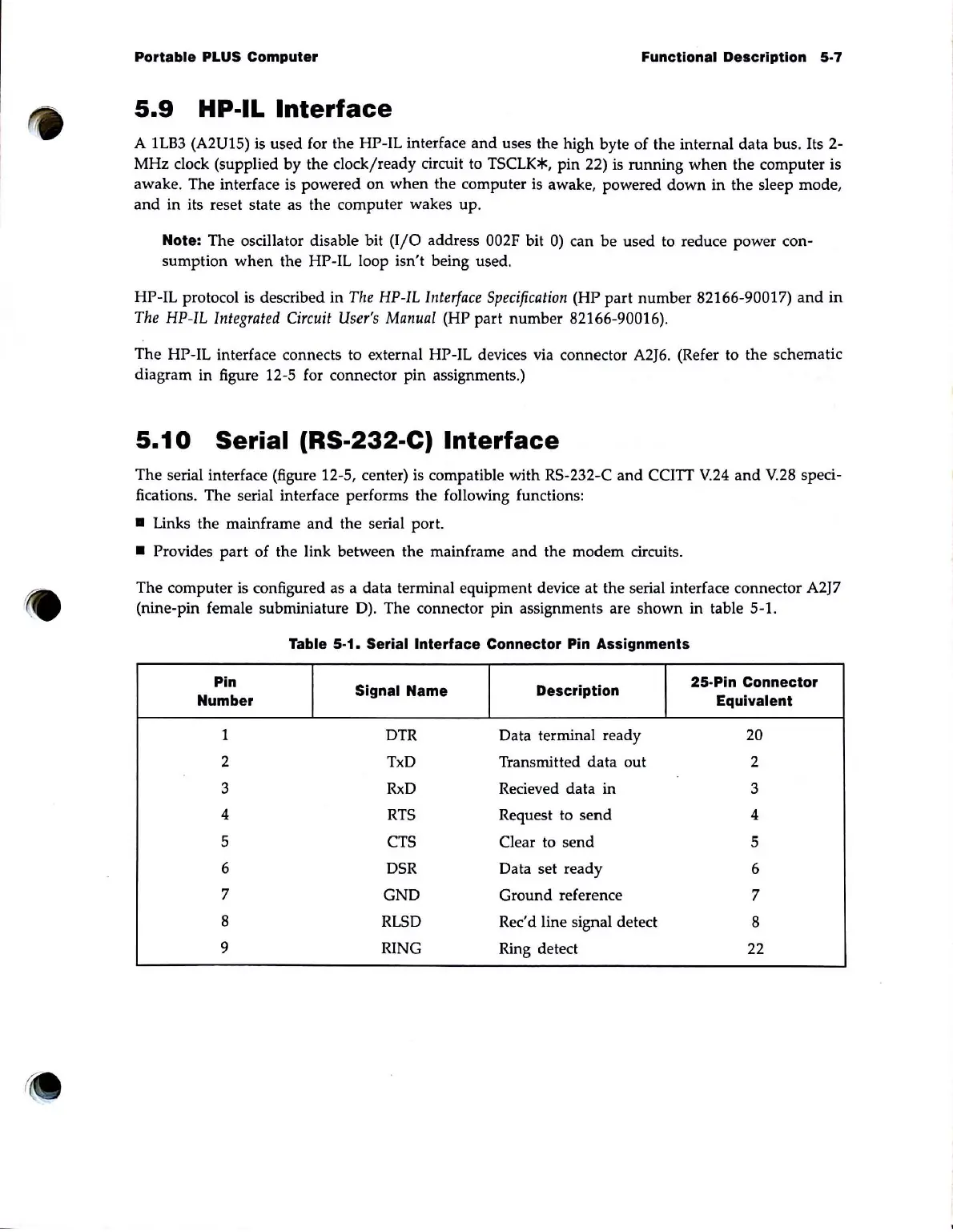
Table 5-1. Serial Interface Connector Pin Assignments
Pin
Signal Name
Description
25·Pin Connector
Number Equivalent
1 DTR Data terminal ready 20
2 TxD Transmitted data out 2
3
RxD
Recieved data in 3
4
RTS
Request to
send
4
5 CTS Clear to send 5
6 DSR
Data set ready 6
7
GND Ground reference
7
8
RLSD
Rec'd line signal detect
8
9
RING
Ring detect 22