Portable
PLUS
Computer
Reference
Information
10-11
1
0.5.3
Diagnostic Module
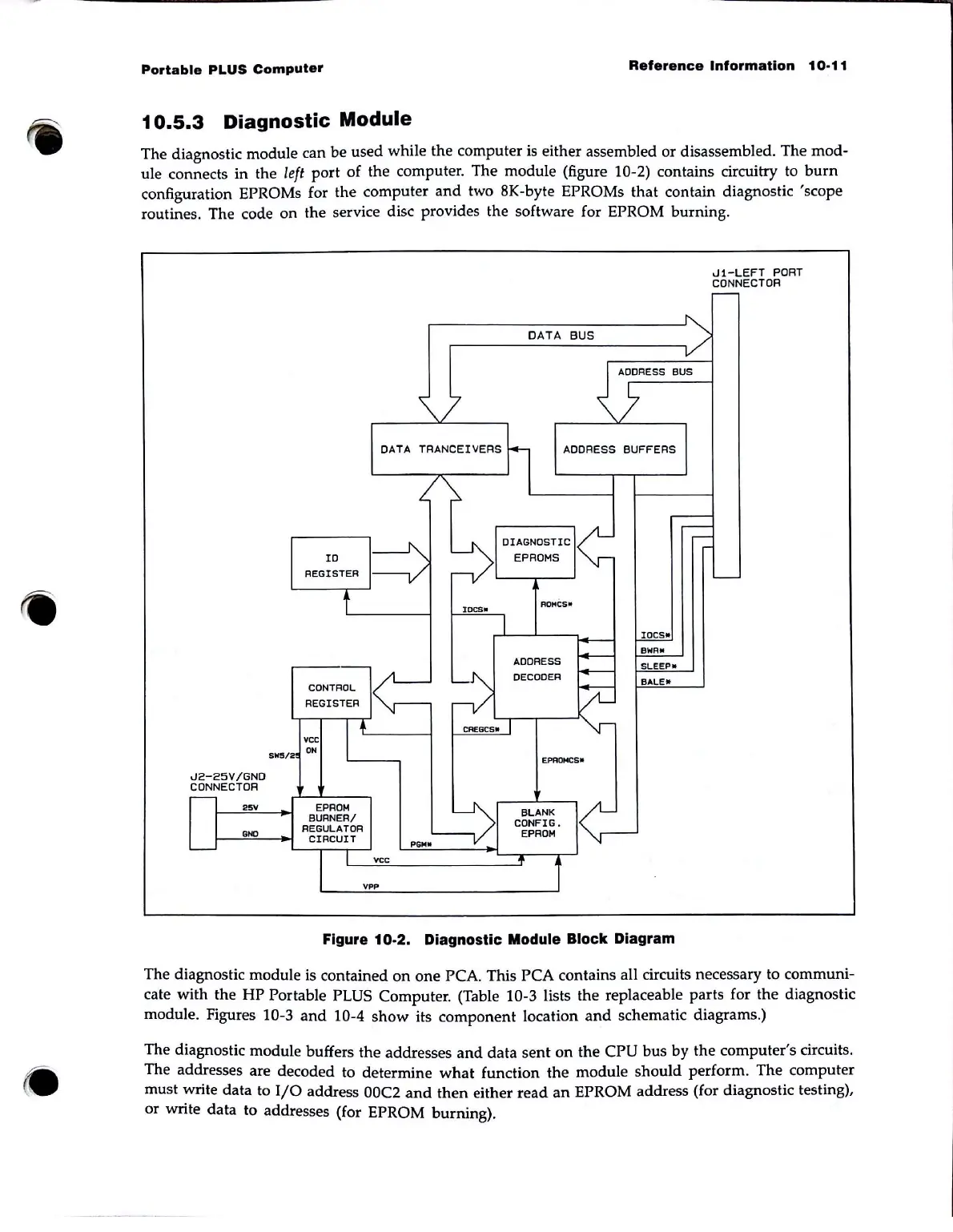
The diagnostic module can
be
used while the computer is either assembled or disassembled. The mod-
ule connects in the left port of the computer. The module (figure 10-2) contains circuitry
to
burn
configuration EPROMs for the computer
and
two 8K-byte EPROMs that contain diagnostic 'scope
routines. The code on the service disc provides the software for EPROM burning.
J2-25V/GND
CDNNECTOR
25V
ID
REGISTER
CONTROL
REGISTER
vee
SNS/2
ON
EPROM
BURNER/
I--.....:::GNO=--Jo-!
Rg~~~i~R
DATA
TRANCEIVERS
vee
vpp
DATA
BUS
ADDRESS
BUFFERS
EPAOMCS_
IOCS"
BWA*
SLEEP.
BALE_
Figure 10-2. Diagnostic Module Block Diagram
J1-LEFT
PORT
CONNECTOR
The diagnostic module is contained
on
one
PCA. This PCA contains
an
circuits necessary to communi-
cate with the
HP
Portable PLUS Computer. (Table 10-3 lists the replaceable parts for the diagnostic
module. Figures 10-3
and
10-4
show
its component location
and
schematic diagrams.)
The diagnostic module buffers the addresses
and
data
sent
on
the CPU bus
by
the computer's circuits.
The addresses are decoded to determine
what
function
the
module should perform. The computer
must write data to
I/O
address 00C2
and
then
either read
an
EPROM address (for diagnostic testing),
or write data to addresses (for EPROM burning).