Portable
PLUS
Computer
Trouble.hootlng
8·15
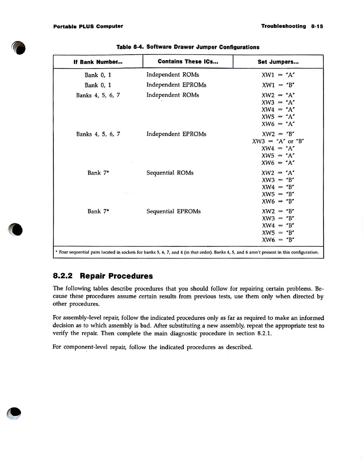
Table 8·4. Software Drawer Jumper Configurations
If
Bank Number ...
I
Contains These ICs ...
I
Set Jumpers ...
Bank
0,
1
Independent
ROMs
XWI
=
"A'"
Bank
0,
1
Independent
EPROMs
XWI
= "B'
Banks 4,
5,
6,
7
Independent
ROMs
XW2
=
'A'
XW3
=
'A'
XW4
=
"A'
XW5
=
"A"
XW6
=
'A"
Banks
4,
5,
6,
7 Independent EPROMs
XW2
=
"B"
XW3
= "
A'
or 'B"
XW4
=
'A'
XW5
=
"A"
XW6
=
"A'
Bank
7·
Sequential ROMs
XW2
=
"A'
XW3
=
"B'
XW4
=
'B'
XW5
=
"B'
XW6
=
'B'
Bank
7·
Sequential EPROMs
XW2
=
'B'
XW3
=
' B'
XW4
=
'B'
XW5
=
'B'
XW6
=
"B"
• Four sequential pairs located in sockets (or banks 5,
6,
7,
and
4 (in that order). Banks
4,
5,
and
6 aren't
pr
ese
nt
in this configuration.
8.2.2
Repair Procedures
The following tables describe procedures that you should follow for repairing certain problems. Be-
cause these procedures assume certain results from previous tests, use them only
when
directed
by
other procedures.
For assembly-level repair, follow the indicated procedures only as far as required to make
an
informed
decision as to which assembly
is
bad. After substituting a
new
assembly, repeat
the
appropriate test to
verify the repair. Then complete the main diagnostic procedure in section 8.2.1.
For component-level repair, follow
the
indicated procedures as described.