Portable
PLUS
Computer
Functional
Description
5·19
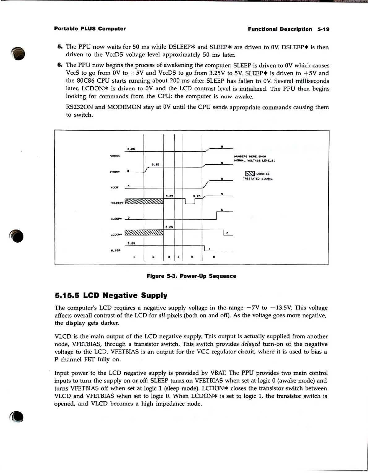
5.
The
PPU
now
waits for 50
ms
while
DSLEEP*
and
SLEEP* are driven to
OV.
DSLEEP*
is
then
driven to
the
VccDS voltage level approximately 50
ms
later.
6.
The
PPU
now
begins the process
of
awakening the computer: SLEEP is driven to
OV
which causes
VccS to go from
OV
to
+5V
and
VccDS to go from 3.25V to
SV
. SLEEP* is driven to
+SV
and
the 80C86
CPU
starts
running
about
200 ms after SLEEP
has
fallen to
OV.
Several milliseconds
later,
LCDON*
is driven to
OV
and
the LCD contrast level is initialized. The
PPU
then
begins
looking for
commands
from the CPU: the computer is
now
awake.
RS2320N
and
MODEMON stay
at
OV
until
the
CPU
sends
appropriate commands causing
them
to switch.
' .
05
VOCOS
..
..
""ON'
0
;'
veeo
0
DSLEEPIf
0
CO""""
1/
'(
/
//
//J
3 .
iZ5
•
2
/
..
..
LI
3 .
25
I 0
•
.
•
•
•
•
•
•
•
0
""""'ERS
HE
RE
$HOW
Hl()AMAl.
VOLTAGE
LEVELS.
~
DENOTES
TAlSTATEO SIG/tAt..
Figure
5·3.
Power·Up Sequence
5.15.5
LCD
Negative
Supply
The computer's LCD requires a negative supply voltage in the range
-7V
to
-13
.
SV.
This voltage
affects overall contrast
of
the LCD for all pixels (both
on
and
off). As the voltage goes more negative,
the display gets darker.
VLCD
is
the
main
output
of
the LCD negative supply. This
output
is actually supplied from
another
node, VFETBIAS, through a transistor switch. This switch provides delayed
turn-on
of
the negative
voltage to the LCD.
VFETBIAS
is
an
output
for the vce regulator circuit,
where
it is used to bias a
P-channel FET fully on.
Input
power to the LCD negative supply
is
provided by
VBAT
. The
PPU
provides two
main
control
inputs to
turn
the supply
on
or
off: SLEEP turns
on
VFETBIAS
when
set at logic 0 (awake mode)
and
turns VFETBIAS off
when
set
at
logic 1 (sleep mode).
LCDON*
closes the transistor switch between
VLCD
and
VFETBIAS
when
set to logic
O.
When
LCDON*
is
set to logic
1,
the transistor switch is
opened,
and
VLCD becomes a high impedance node.