5-8 Functional Description
Portable PLUS Computer
The serial interface
is
split between a ILKS serial
port
(A2U18)
and
the PPU (A2U17). Multicontroller
A2U18 controls frame formatting
and
receiver/transmitter status.
When the interface is open-circuited, its signal status
is
as follows: RING reads as a
'0';
RLSD,
CTS,
DSR
,
and
the operation status register serial ' data in' bit
(I/O
address 0048 hex, bit
6)
read as a
'I'.
In sleep mode, A2U18
is
powered
and
is
then in its
own
sleep mode,
and
serial
port
control registers
remain in their programmed state.
Power control for the interface's line drivers is provided by the PPU (A2U17) at PC2, pin 26. The PPU
also controls the serial interface's
RTS
and
DTR
lines:
PA6
and
PA7,
pins 5
and
4
on
the PPU.
5.11
Video
Interface
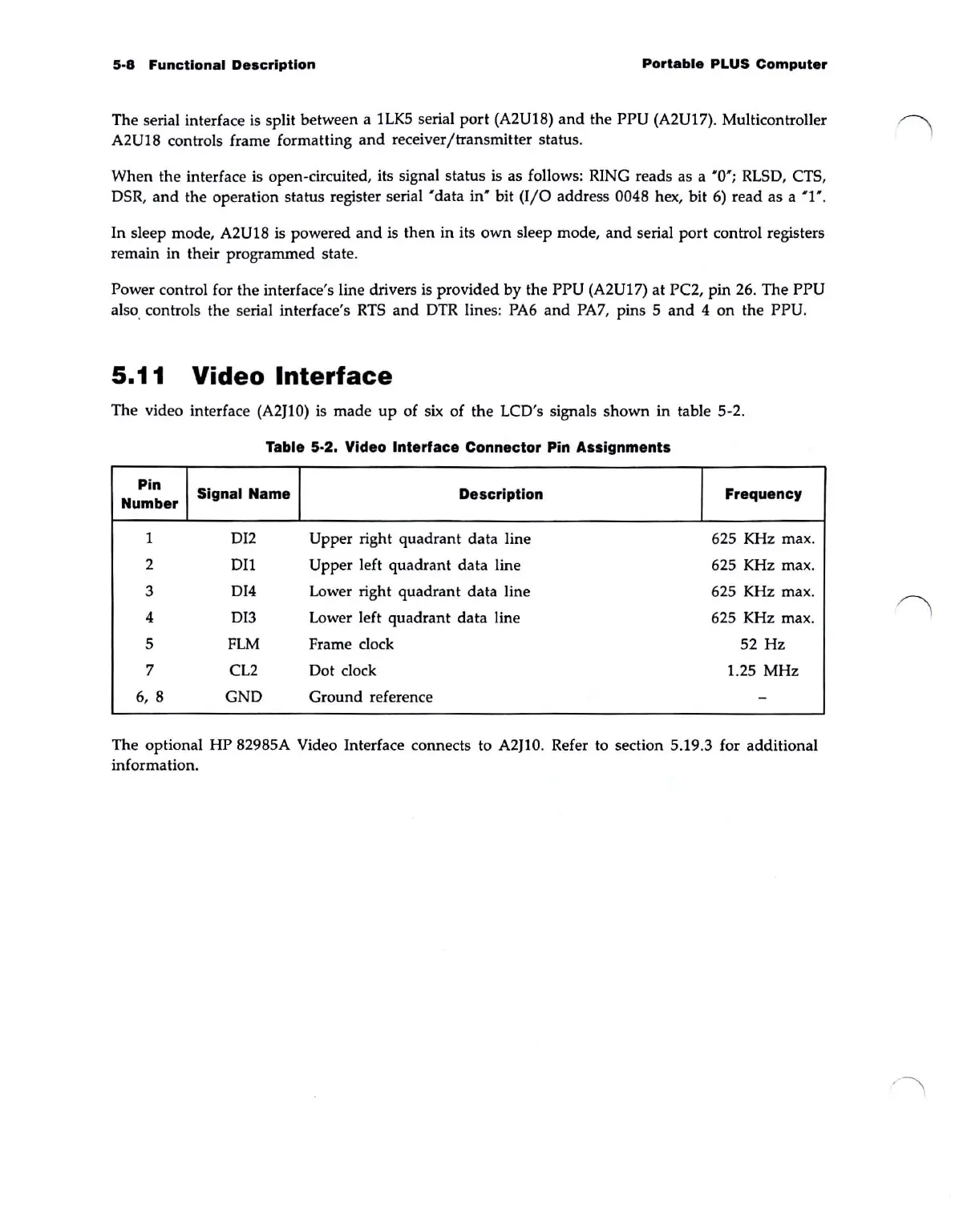
The video interface (A2JlO) is made
up
of
six
of the LCD's signals shown in table 5-2.
Table 5-2. Video
Interface
Connector Pin Assignments
Pin
Signal
Name
Description Frequency
Number
1
DI2
Upper right quadrant data line 625 KHz max.
2
DI1
Upper left quadrant data line 625 KHz max.
3 DI4 Lower right quadrant data line 625 KHz max.
4
DI3 Lower left quadrant data line
625 KHz max.
5
FLM
Frame
dock
52 Hz
7
CL2
Dot dock 1.25 MHz
6, 8
GND Ground reference
-
The optional HP 82985A Video Interface connects to A2JI0. Refer to section 5.19.3 for additional
information.