8·30
Troubleshooting
Portable
PLUS
Computer
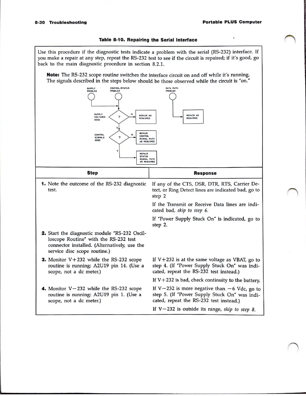
Table
8·10.
Repairing
the
Serial
Interface
Use this procedure if the diagnostic tests indicate a problem with the serial (RS-232) interface.
If
you make a repair at any step, repeat the RS-232 test to see if the circuit is repaired; if it's good, go
back to the main diagnostic procedure in section 8.2.1.
Note: The RS-232 scope routine switches the interface circuit on
and
off while it's running.
The signals described in the steps below should be those observed while the circuit is
'on:
SUPPLY
PflOllL[H
SUPPLY
VOLT AGES
GOOO
CONTROL.
'5I
GH
"'LS
0000
Step
CONTROL/STATUS
~OelE"
1.
Note the outcome of the RS-232 diagnostic
test.
2.
Start the diagnostic module 'RS-232 Oscil-
loscope
Routine'
with the RS-232 test
connector installed. (Alternatively, use the
service disc scope routine.)
3.
Monitor V + 232 while the RS-232 scope
routine is running:
A2U19 pin 14. (Use a
scope,
not
a dc meter.)
4.
Monitor V - 232 while
the
RS-232 scope
routine is running:
A2U19 pin
1.
(Use a
scope, not a dc meter.)
DATA
PAtH
PR08LiEJoI
Response
If
any of the CTS, DSR, DTR, RTS, Carrier De-
tect, or Ring Detect lines are indicated bad, go to
step 2
If
the Transmit or Receive Data lines are indi-
cated bad,
skip
to
step
6.
If
'Power
Supply Stuck
On'
is indicated, go to
step
2.
If
V+232
is
at the same voltage as
VBAT,
go to
step
4.
(If 'Power Supply Stuck
On'
was
indi-
cated, repeat the RS-232 test instead.)
If
V + 232
is
bad, check continuity to
the
battery.
If
V-232
is more negative
than
-6
Vdc, go to
step 5.
(If
'Power
Supply Stuck
On'
was
indi-
cated, repeat the RS-232 test instead.)
If
V - 232 is outside its range,
skip
to
step
8.