5-4
Functional
Description
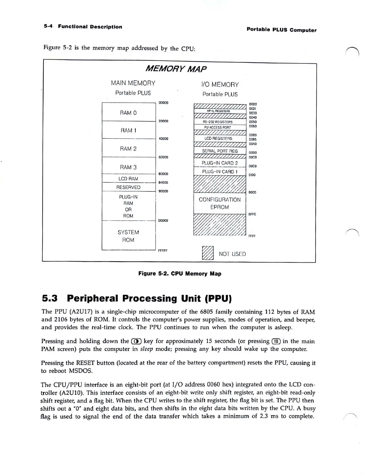
Figure 5-2 is the memory map addressed by the CPU:
MEMORY
MAP
r-
MA
IN
MEM
OR
Y
Po
r
ta
bl
e
PL
US
R
AM
0
RAM
1
R
AM
2
RA
M 3
LCD
R
AM
R
ESERVED
P
LUG
-IN
R
AM
OR
ROM
--
SYSTEM
ROM
110
ME
MO
RY
Po
rtable PLUS
00000
HP-Il
REGISTERS
20000
RS-232
REG
I
STERS
PU
ACCESS
PORT
40000
LCD
REG
I
STERS
SERIAL
POR
T REG
60000
PL
UG-
IN
CAR
D 2
80000
84000
90000
I
00000
FFITF
~
NOT
USED
Figure 5-2. CPU Memory Map
5.3
Peripheral
Processing
Unit (PPU)
Portable
PLUS
Computer
0000
0021
0030
0040
0050
0060
0080
0085
OOM
0080
ooco
The
PPU
(A2U17) is a Single-chip microcomputer
of
the 6805 family containing 112 bytes
of
RAM
a
nd
2106 bytes
of
ROM. It controls the computer's power supplie
s,
modes of operation,
and
beeper,
and
provides the real-time clock. The PPU continues to run
when
the computer
is
asleep.
Pressing
and
holding
down
the @ key for approximately
15
seconds (or pressing ® in the main
PAM screen)
puts
the computer
in
s
leep
mod
e;
pressing any key should wake
up
the computer.
Pressing the RESET
button
(located
at
the rear of the battery compartment) resets the PPU, causing it
to reboot MSDOS.
Th
e CPU
/PPU
interface is
an
eight-bit port (at
I/O
addr
ess 0060 hex) integrated onto the LCD con-
troller (A2U10). This interfa
ce
consists of
an
ei
g
ht
-bit write only shift registe
r,
an eight-bit read-only
shift registe
r,
a
nd
a flag bi
t.
When
the
CPU writes to the shift registe
r,
the
fl
ag bit
is
se
t.
The PPU then
shifts
out
a
'0
'
and
eight data bits,
and
then
shifts in the eight data bits written by the CPU. A
bu
sy
flag is used to signal the e
nd
of
th
e data transfer which takes a minimum
of
2.3 ms to complet
e.