Portable PLUS Computer
Troubleshooting 8-31
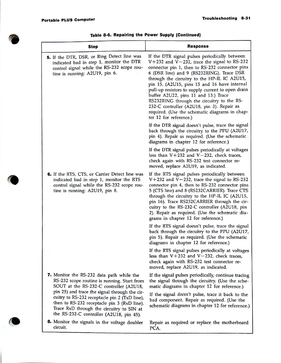
Table
8-6.
Repairing
the
Power
Supply (Continued)
Step
5.
If
the
DTR,
DSR, or Ring Detect line was
indicated bad in step
1,
monitor the DTR
control signal while the RS-232 scope rou-
tine is running: A2U19,
pin
6.
6.
If
the
RTS,
CTS, or Carrier Detect line was
indicated bad in step L monitor the
RTS
control signal while the RS-232 scope rou-
tine is running: A2U19, pin
8.
7.
Monitor the RS-232 data
path
while the
RS-232 scope routine is running. Start from
SOUT
at
the RS-232-C controller (A2UI8,
pin 25)
and
trace the signal through the cir-
cuitry to RS-232 receptacle pin 2 (TxD line),
then to RS-232 receptacle pin 3 (RxD line).
Trace
RxD
through the circuitry to SIN
at
the RS-232-C controller (A2UI8, pin 45).
8.
Monitor the signals in the voltage doubler
circuit.
I
Response
If
the DTR signal pulses periodically between
V+232
and
V-232,
trace the signal to RS-232
connector pin 1, then to RS-232 connector pins
6
(DSR
line)
and
9 (RS232RING). Trace
DSR
through the circuitry to the HP-IL IC A2U15,
pin 15. (A2UI5, pins 15
and
16 have internal
pull-up resistors to supply current to
open
drain
buffer A2U22, pins
11
and 13.) Trace
RS232RING through the circuitry to the
RS-
232-C controller (A2U18, pin
3)
. Repair as
required. (Use the schematic diagrams in
chap-
ter 12 for reference.)
If
the
DTR
signal doesn't pulse, trace the signal
back through the circuitry to the PPU (A2UI7,
pin 4). Repair as required. (Use the schematic
diagrams in chapter 12 for reference.)
If
the DTR signal pulses periodically at voltages
less than V + 232
and
V - 232, check traces,
check again with RS-232 test connector re-
moved, replace A2U19, as indicated.
If the
RTS
signal pulses periodically between
V + 232
and
V - 232, trace the signal to RS-232
connector pin 4, then
to
RS-232 connector pins
5 (CTS line)
and
8 (RS232CARRIER). Trace CTS
through the circuitry to the HP-IL
IC
(A2UI5,
pin 16). Trace RS232CARRIER through the cir-
cuitry to the RS-232-C controller (A2UI8, pin
2).
Repair as required. (Use the schematic dia-
grams in chapter
12
for reference.)
If
the
RTS
signal doesn't pulse, trace the signal
back through the circuitry to the PPU (A2U17,
pin 5). Repair as required. (Use the schematic
diagrams in chapter
12
for reference.)
If
the
RTS
signal pulses periodically at voltages
less
than
V + 232
and
V - 232, check traces,
check again with RS-232 test connector re-
moved, replace A2U19, as indicated.
If
the signal pulses periodically, continue tracing
the signal through the circuitry. (Use the sche-
matic diagrams in chapter 12 for reference.)
If
the Signal doesll't pulse, trace it back to
the
bad
component. Repair as required. (Use
the
schematic diagrams in chapter 12 for reference.)
Repair as required or replace the motherboard
PCA.