10-8
Reference
Information
Portable
PLUS
Computer
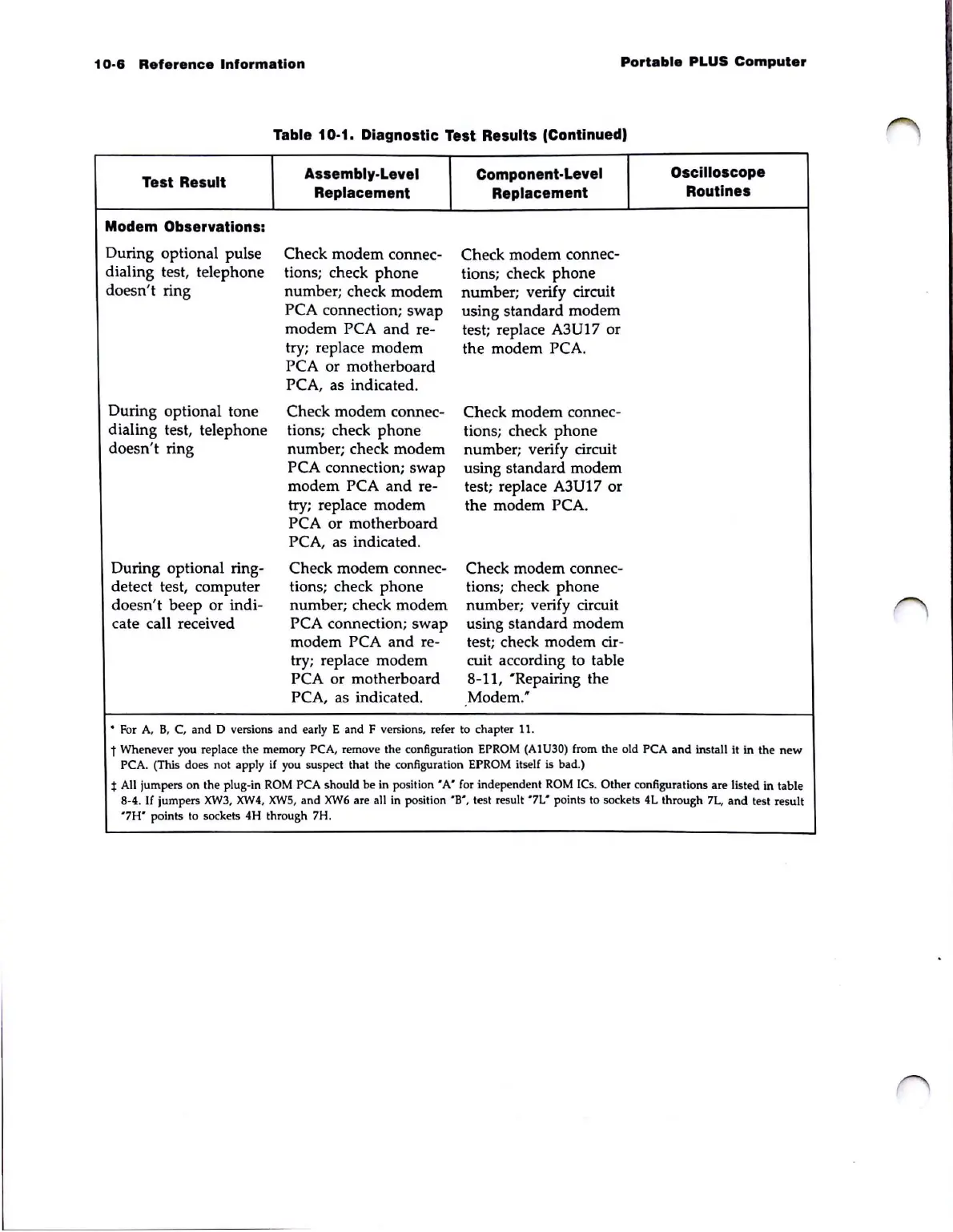
Table 10-1. Diagnostic Test Results (Continued,
Test Result
Assembly-Level
Component-Level
Oscilloscope
Replacement Replacement
Routines
Modem Observations:
During optional pulse
Check
modem
connec-
Check modem connec-
dialing test, telephone
tions; check
phone
tions; check
phone
doesn't ring
number; check modem
number
; verify circuit
PCA connection; swap
using standard
modem
modem PCA
and
re-
test; replace
A3
U 17 or
try; replace modem
the modem PCA.
PCA or motherboard
PCA, as indicated.
During optional tone
Check modem connec-
Check modem connec-
dialing test, telephone
tions; check
phone
tions; check
phone
doesn't ring
number; check modem
number; verify circuit
PCA connection; swap
using standard modem
modem PCA
and
re-
test; replace A3U17 or
try; replace modem the modem PCA.
PCA or motherboard
PCA, as indicated.
During optional ring-
Check modem connec-
Check modem connec-
detect test, computer tions; check
phone
tions; check
phone
doesn't
beep
or indi- number; check modem number; verify circuit
cate call received PCA connection;
swap
using standard modem
modem PCA
and
re- test; check modem cir-
try; replace modem cuit according to table
PCA or motherboard 8-11, "Repairing the
PCA, as indicated . Modem."
..
For
A,
B,
C, and D versions and
earl
y E
and
F ve
rsi
ons, refer
to
ch
a
pter
11.
t Whenever you replace the memory PCA, remove the configuration EPROM (AIU30) from the old PCA
and
install it
in
the
new
PCA. (This
do
es not apply if you suspect that the configuration EPROM itself is bad.)
t All jumpers on the plug-in
ROM
PCA should be in
position'
A'
for independent
ROM
ICs.
Oth
er configurations are listed in table
8-4.
If
jumpers
XW3, XW4.
XW5
, and
XW6
are all in position
'B',
test result
'7L'
points to sockets
4L
through 7L.
and
test result
'7H'
points to sockets 4H through 7H.