Portable
PLUS
Computer
Product
History
11-11
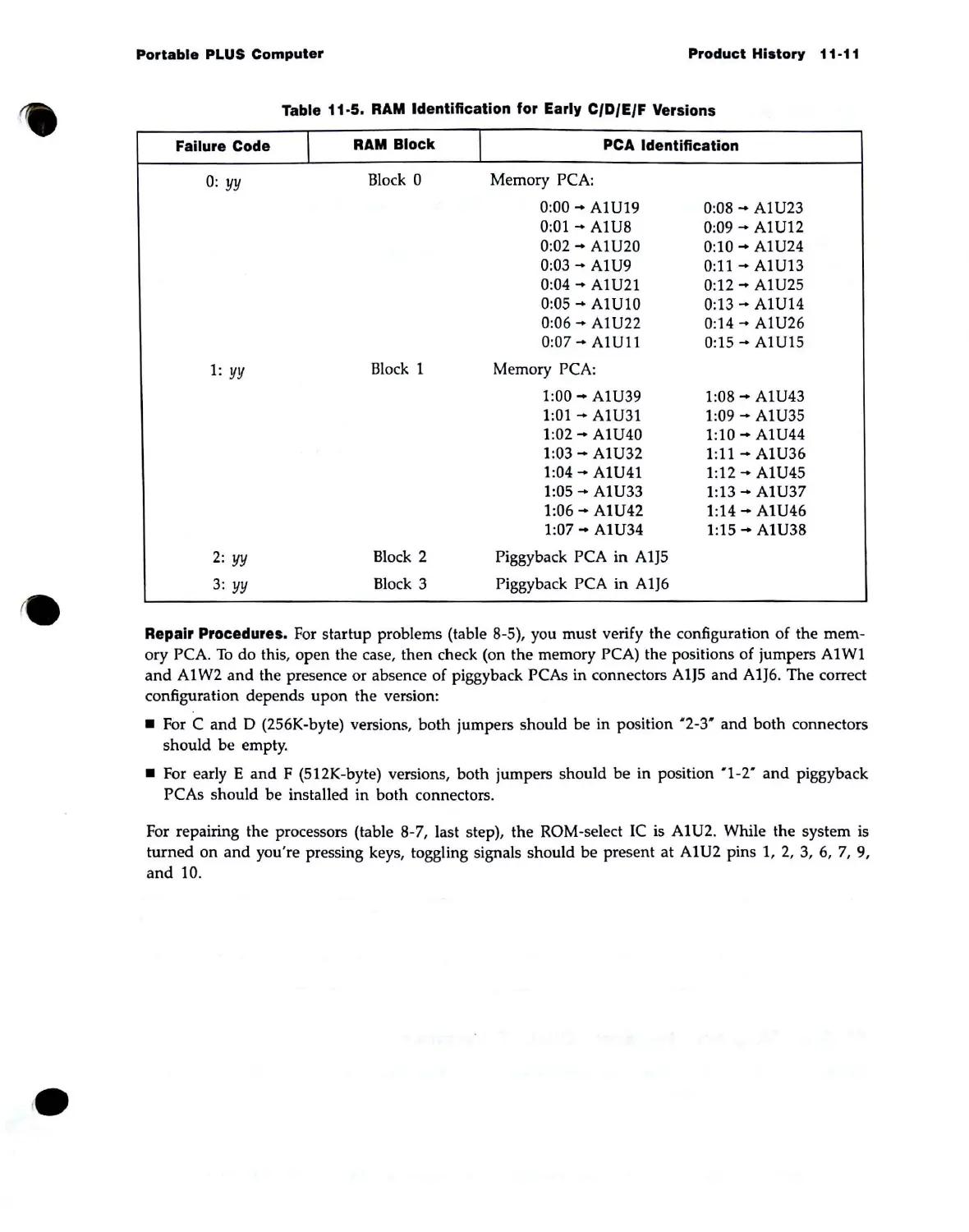
Table 11-5.
RAM
Identification for Early CIDIEIF Versions
Failure Code
I
RAM
Block
I
PCA
Identification
0:
yy
Block 0 Memory PCA:
0:00
-+
AlU19
0:08
-+
AlU23
0:01
-+
AlU8
0:09
-+
AlU12
0:02
-+
AlU20
0:10
....
AlU24
0:03
-+
AlU9
0:11
-+
AlU13
0:04
-+
AlU21 0:12
....
AlU25
0:05
-+
AlU10
0:13
....
AlU14
0:06
-+
AlU22
0:14
....
AlU26
0:07
....
AlUl1
0:15""
AlU15
1:
yy
Block 1 Memory PCA:
1:00
....
AlU39
1:08
....
AlU43
1:01
....
AlU31
1:09
-+
AlU35
1:02
....
AlU40
1:10
-+
AlU44
1:03
....
AlU32
1:
11
-+
AlU36
1:04
-+
AlU41
1:12
-+
AlU45
1:05
....
AlU33
1:13
-+
AlU37
1:06
-+
AlU42
1:14
-+
AlU46
1:07
....
AlU34
1:15
-+
AlU38
2:
yy
Block 2 Piggyback PCA
in
A1J5
3:
yy
Block 3
Piggyback PCA in
A1J6
Repair Procedures.
For
startup problems (table 8-5), you must verify the configuration
of
the mem-
ory PCA.
To
do this, open the case,
then
check (on the memory PCA) the positions of jumpers
Al
WI
and
Al
W2
and
the presence or absence of piggyback PCAs in connectors
A1J5
and A1J6. The correct
configuration depends upon the version:
• For C
and
D (256K-byte) versions, both jumpers should be in position "2-3"
and
both connectors
should be empty .
• For early E
and
F (512K-byte) versions,
both
jumpers should be in position "1-2"
and
piggyback
PCAs should be installed in both connectors.
For repairing the processors (table 8-7, last step), the ROM-select
IC
is
Al
U2. While the system
is
turned
on
and
you're pressing keys, toggling signals should be present
at
AIU2
pins 1,
2,
3,
6,
7,
9,
and
10.