Portable
PLUS
Computer
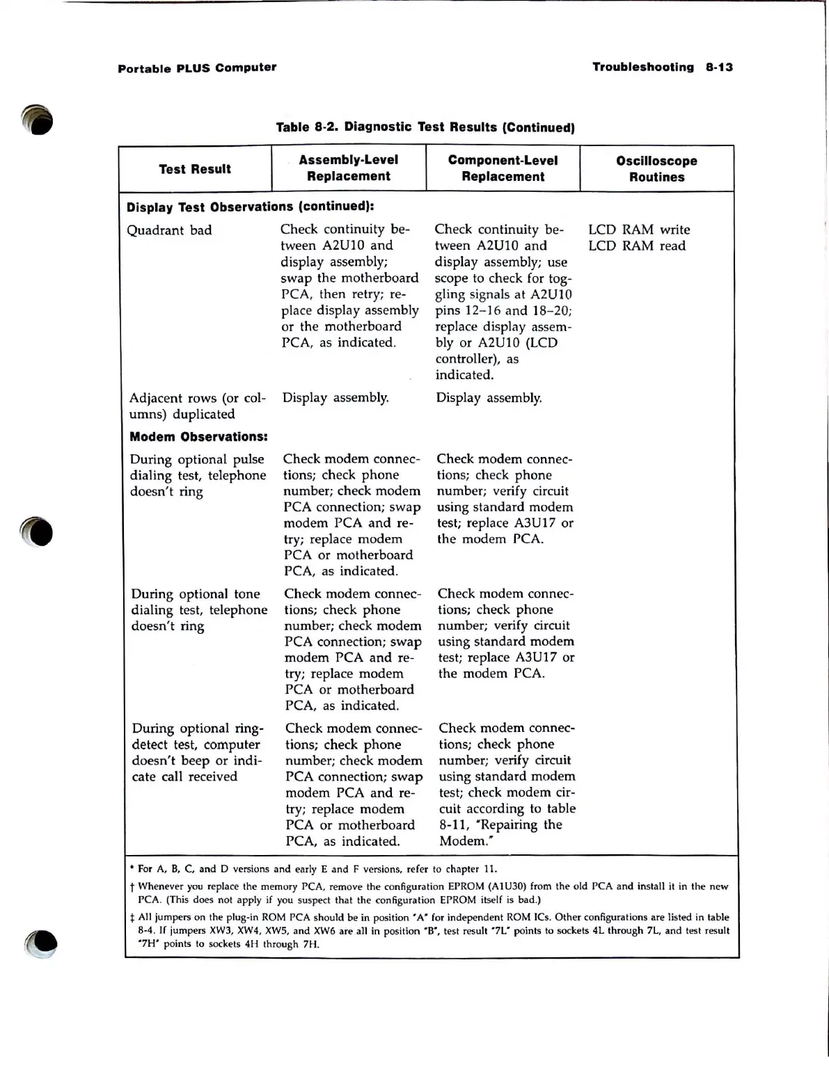
Table 8-2. Diagnostic Test Results (Continued)
Test Result
Assembly-Level
Replacement
Display Test Observations (continued):
Quadrant
bad
Check continuity
be-
tween A2U10
and
display assembly;
swap
the
motherboard
PCA, then retry; re-
place display assembly
or the motherboard
PCA, as indicated.
Adjacent rows (or col- Display assembly.
umns) duplicated
Modem Observations:
During optional pulse
dialing test, telephone
doesn't
ring
During optional tone
dialing test, telephone
doesn't
ring
During optional
ring-
detect test, computer
doesn't
beep
or
indi-
cate call received
Check modem connec-
tions; check
phone
number; check
modem
PCA connection;
swap
modem PCA
and
re-
try; replace
modem
PCA or motherboard
PCA, as indicated.
Check
modem
connec-
tions; check
phone
number; check
modem
PCA connection;
swap
modem
PCA
and
re-
try; replace
modem
PCA or motherboard
PCA, as indicated.
Check
modem
connec-
tions; check
phone
number; check
modem
PCA connection;
swap
modem
PCA
and
re-
try; replace
modem
PCA or motherboard
PCA, as indicated .
Component-Level
Replacement
Check continuity
be-
tween A2U10
and
display assembly; use
scope to check for tog-
gling signals
at
A2U10
pins
12-16
and
18-20;
replace display assem-
bly or
A2U10 (LCD
controller), as
indicated.
Display assembly.
Check modem
connec-
tions; check
phone
number; verify circuit
using standard modem
test; replace
A3U17 or
the modem PCA.
Check modem connec-
tions; check
phone
number; verify circuit
using
standard
modem
test; replace
A3U17
or
the modem PCA.
Check
modem
connec-
tions; check
phone
number; verify circuit
using standard
modem
test; check
modem
cir-
cuit according to table
8-11,
'Repairing the
Modem."
• For
A,
B,
C.
and
D versions
and
early E
and
F versions, refer to chapter 1 J.
Troubleshooting
8-13
Oscilloscope
Routines
LCD RAM write
LCD RAM
read
t Whenever
you
replace the memory PCA. remove the configuration EPROM (AIU30) from the old PCA and install it in the new
PCA. (This does not apply
if
you suspect that the configuration EPROM itse
lf
is
bad.)
t
All
jumpers on the plug-in
ROM
PCA should be in
position'
A"
for independent
ROM
ICs.
Other
configurations are listed in table
8-4.
If
jumpers
XW3,
XW4, XW5,
and
XW6
are all in position
-B-,
test result '7L- points to sockets 4L through
7L,
and
test result
"7H'
points to sockets 4H through 7H.