8-22
Troubleshooting
Portable
PLUS
Computer
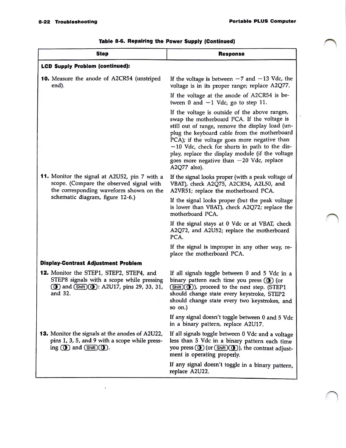
Table 8-6. Repairing the Power Supply (Continued)
Step
LCD Supply Problem (continued):
10.
Measure the anode of A2CR54 (unstriped
end).
11.
Monitor the signal at A2U52, pin 7 with a
scope. (Compare the observed signal with
the corresponding waveform shown
on
the
schematic diagram, figure 12-6.)
Dlsplay·Contrast Adjustment Problem
12.
Monitor the STEP1, STEP2, STEP4,
and
STEPS signals with a scope while pressing
(ID
and
(Shift)(ID:
A2U17, pins
29,
33, 31,
and
32.
13.
Monitor the signals at the anodes of A2U22,
pins
1,
3,
5,
and
9 with a scope while press-
ing
(ID
and
(Shift
)mJ
.
I
Response
If
the voltage is between
-7
and
-13
Vdc, the
voltage
is
in its proper range; replace A2Q77.
If
the voltage at the anode of A2CR54 is be-
tween 0
and
- 1 V dc, go
to
step 11.
If
the voltage
is
outside of the above ranges,
swap the motherboard
PCA.
If
the voltage is
still out of range, remove the display load
(un-
plug the keyboard cable from the motherboard
PCA);
if
the voltage goes more negative than
-10
Vdc,
check for shorts in path to the dis-
play, replace the display module (if the voltage
goes more negative than
-20
Vdc, replace
A2Q77 also).
If
the signal looks proper (with a peak voltage of
VBAT),
check A2Q75, A2CR54, A2L50,
and
A2VR5l; replace the motherboard PCA.
If
the signal looks proper (but the peak voltage
is
lower than
VBAT),
check A2Q72; replace the
motherboard
PCA.
If
the signal stays at 0 Vdc or at
VBAT,
check
A2Q72, and
A2U52; replace the motherboard
PCA.
If the signal is improper in any other way, re-
place the motherboard PCA.
If
all signals toggle between 0
and
5 Vdc in a
binary pattern each time you press
(ID
(or
(
Shift
)(ID),
proceed to the next step. (STEP I
should change state every keystroke, STEP2
should change state every two keystrokes,
and
so on.)
If
any signal doesn't toggle between 0
and
5 Vdc
in a binary pattern, replace
A2U17.
If
all signals toggle between 0 Vdc
and
a voltage
less than 5 Vdc in a binary
pattern
each time
you press
UU (or (
Shift
)UU), the contrast adjust-
ment is operating properly.
If
any signal doesn't toggle in a binary pattern,
replace
A2U22.