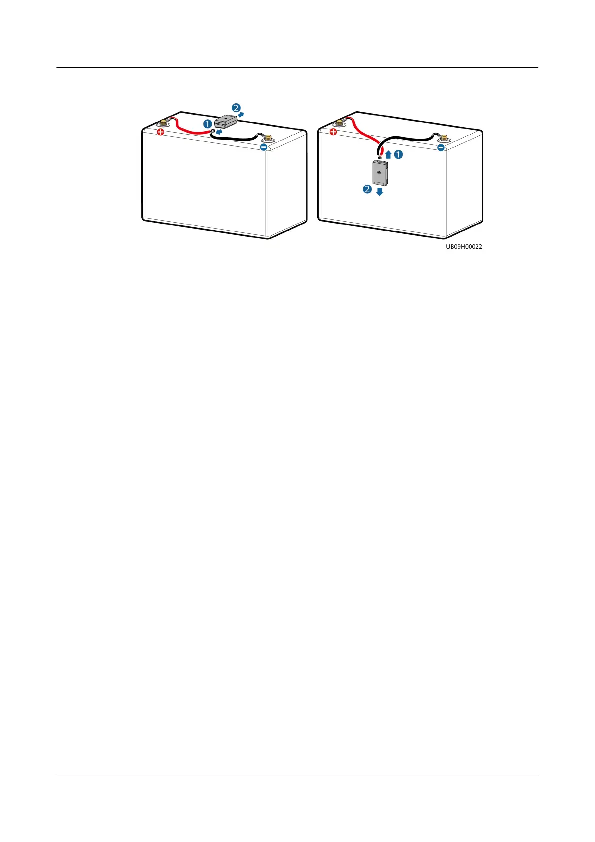
Figure 5-52 Removing an iBAT
Step 2 Secure the new iBAT on the fastener, and connect the iBAT cables.
Step 3 Press the iBOX networking switch for 2 seconds. The RF_Z indicator on the iBOX
changes from blinking green at long intervals to blinking green at super short
intervals, which indicates that the iBOX is being networked.
Step 4 Hold down the iBAT networking switch for 2 seconds. When the RUN/ALM
indicator turns from steady red to blinking green at short intervals, and
nally to
blinking green at long intervals, the iBAT connects to the iBOX network. A newly
added iBAT will replace the iBAT that has failed in communication. If multiple
iBATs fail in communication, the newly added iBATs will replace them in ascending
order of address.
Step 5 Press the networking switch on the iBOX for 2 seconds. When the RF_Z indicator
on the iBOX and the RUN indicator on the iBAT turn from blinking green at super
short intervals to blinking green at long intervals, the replacement is complete.
Step 6 Log in to the ECC800-Pro WebUI and verify that the iBAT parameters are
displayed normally.
----End
5.4.5 Replacing a Smart ETH Gateway
Impact on the System
The facilities connected to the faulty ETH gateway cannot be monitored on the
ECC800.
Preparations
● Tools: ESD wrist strap, ESD gloves, Phillips screwdriver, step ladder, labels,
marker
● Material: ETH gateway
Procedure
Step 1 Label each cable based on the corresponding ports on the smart ETH gateway.
Step 2 Disconnect cables from the smart ETH gateway.
FusionModule2000 Smart Modular Data Center
Maintenance Guide (Fusion Module Actuator) 5 Parts Replacement
Issue 01 (2020-12-25) Copyright © Huawei Technologies Co., Ltd. 100