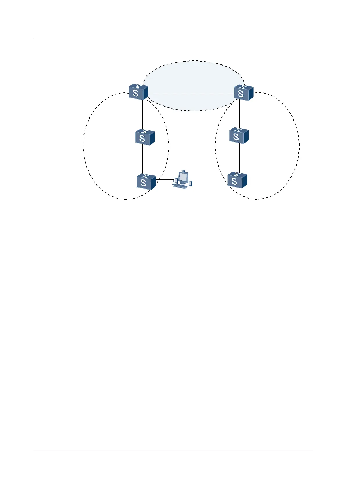
Figure 4-12 Networking diagram for configuring OSPF GTSM
Switch A
Switch B
Switch D
XGE0/0/1
192.168.0.1/24
XGE0/0/1
192.168.0.2/24
XGE0/0/2
192.168.2.1/24
XGE0/0/1
192.168.2.2/24
Area0
XGE0/0/2
192.168.1.1/24
XGE0/0/2
172.17.1.1/24
Switch C
XGE0/0/1
192.168.1.2/24
Area1
XGE0/0/2
172.16.1.1/24
Area2
XGE0/0/2
172.16.1.2/24
XGE0/0/2
172.17.1.2/24
Switch E
Switch F
PC
Switch Interface VLANIF interface IP address
SwitchA XGigabitEthernet0/0/1 VLANIF 10 192.168.0.1/24
SwitchA XGigabitEthernet0/0/2 VLANIF 20 192.168.1.1/24
SwitchB XGigabitEthernet0/0/1 VLANIF 10 192.168.0.2/24
SwitchB XGigabitEthernet0/0/2 VLANIF 30 192.168.2.1/24
SwitchC XGigabitEthernet0/0/1 VLANIF 20 192.168.1.2/24
SwitchC XGigabitEthernet0/0/2 VLANIF 40 172.16.1.1/24
SwitchD XGigabitEthernet0/0/1 VLANIF 30 192.168.2.2/24
SwitchD XGigabitEthernet0/0/2 VLANIF 50 172.17.1.1/24
SwitchE XGigabitEthernet0/0/2 VLANIF 40 172.16.1.2/24
SwitchF XGigabitEthernet0/0/2 VLANIF 50 172.17.1.2/24
Configuration Roadmap
The configuration roadmap is as follows:
1. Configure basic OSPF functions.
2. Enable GTSM on each switch and specify the valid TTL range of packets.
Data Preparation
To complete the configuration, you need the following data:
l OSPF process number of each switch
S6700 Series Ethernet Switches
Configuration Guide - IP Routing 4 OSPF Configuration
Issue 01 (2012-03-15) Huawei Proprietary and Confidential
Copyright © Huawei Technologies Co., Ltd.
174
 Loading...