network 9.1.1.0 255.255.255.0
peer 9.1.1.1 enable
peer 200.1.2.1 enable
peer 200.1.2.1 route-policy 10 export
#
route-policy 10 permit node 10
apply cost 150
#
return
7.20.9 Example for Configuring BGP GTSM
Networking Requirements
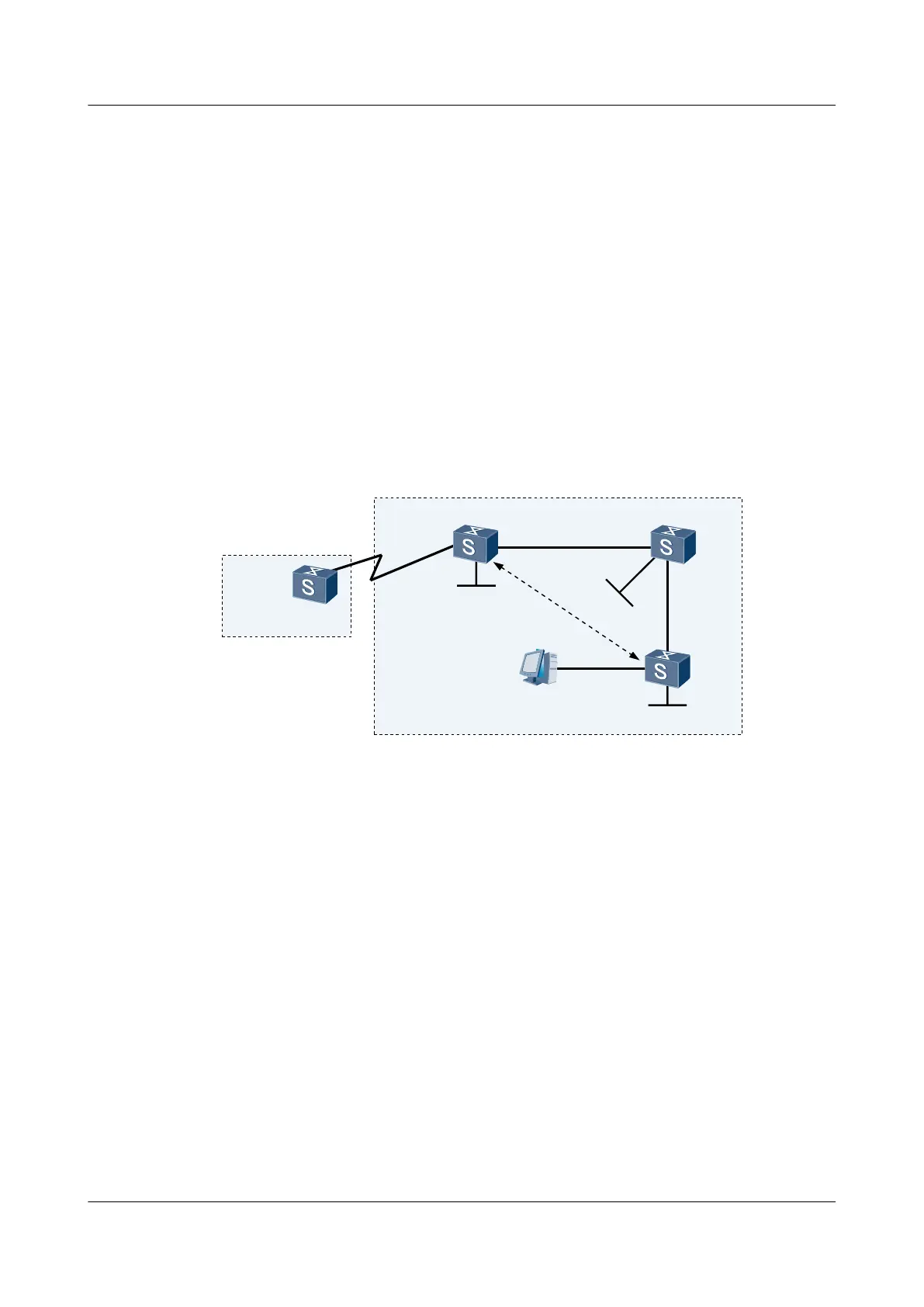
As shown in Figure 7-12, Switch A belongs to AS 10, and Switch B, Switch C, and Switch D
belong to AS 20. BGP is run in the network and BGP GTSM is configured to protect Switch B
against CPU-utilization attacks.
Figure 7-12 Networking diagram for configuring BGP GTSM
SwitchA
PC
AS10
XGE0/0/1
10.1.1.1/24
XGE0/0/1
10.1.1.2/24
XGE0/0/2
20.1.1.1/24
XGE0/0/1
20.1.1.2/24
XGE0/0/2
20.1.2.1/24
XGE0/0/1
20.1.2.2/24
Loopback0
4.4.4.9/32
AS20
Loopback0
2.2.2.9/32
L
o
o
p
b
a
c
k
0
3
.
3
.
3
.
9
/
3
2
EBGP
IBGP
IBGP
I
B
G
P
SwitchB
SwitchC
SwitchD
switch
Interface VLANIF interface IP address
SwitchA XGigabitEthernet0/0/1 VLANIF 10 10.1.1.1/24
SwitchB XGigabitEthernet0/0/1 VLANIF 10 10.1.1.2/24
SwitchB XGigabitEthernet0/0/2 VLANIF 20 20.1.1.1/24
SwitchC XGigabitEthernet0/0/1 VLANIF 20 20.1.1.2/24
SwitchC XGigabitEthernet0/0/2 VLANIF 30 20.1.2.1/24
SwitchD XGigabitEthernet0/0/1 VLANIF 30 20.1.2.2/24
Configuration Roadmap
The configuration roadmap is as follows:
1. Configure OSPF on Switch B, Switch C, and Switch D to implement interworking in AS
20.
2. Set up an EBGP connection between Switch A and Switch B, and set up IBGP connections
between Switch B, Switch C, and Switch D through loopback interfaces.
S6700 Series Ethernet Switches
Configuration Guide - IP Routing 7 BGP Configuration
Issue 01 (2012-03-15) Huawei Proprietary and Confidential
Copyright © Huawei Technologies Co., Ltd.
487
 Loading...