network 9:2:: 64
peer 9:1::1 enable
peer 9:2::1 enable
#
return
8.15.2 Example for Configuring BGP4+ Route Reflectors
Networking Requirements
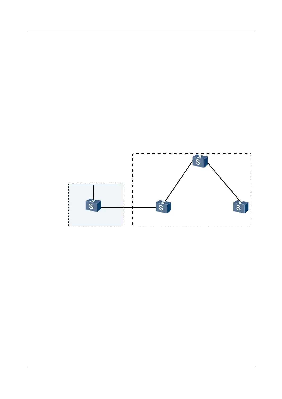
As shown in Figure 8-2, Switch B receives an update packet from Switch A through EBGP and
forwards the packet to Switch C. Switch C is configured as a route reflector and it has two clients,
namely, Switch B and Switch D.
Switch B and Switch D do not need to set up an IBGP connection. After receiving a route update
packet from Switch B, Switch C reflects the packet to Switch D. Similarly, after receiving a
route update packet from Switch D, Switch C reflects the packet to Switch B.
Figure 8-2 Networking diagram for configuring the BGP4+ route reflectors
SwitchA
XGE0/0/2
VLANIF20
1::1/64
SwitchB
SwitchC
SwitchD
AS 100
AS 200
XGE0/0/1
VLANIF10
100::1/96
100::2/96
VLANIF20
XGE0/0/2
X
G
E
0
/
0
/
1
X
G
E
0
/
0
/
2
X
G
E
0
/
0
/
1
X
G
E
0
/
0
/
1
V
L
A
N
I
F
3
0
V
L
A
N
I
F
3
0
V
L
A
N
I
F
4
0
V
L
A
N
I
F
4
0
1
0
1
:
:
2
/
9
6
1
0
1
:
:
1
/
9
6
1
0
2
:
:
1
/
9
6
1
0
2
:
:
2
/
9
6
Device name
Interface VLANIF interface IP address
Switch A XGE0/0/1 VLANIF 10 1::1/64
Switch A XGE0/0/2 VLANIF 20 100::1/96
Switch B XGE0/0/2 VLANIF 20 100::2/96
Switch B XGE0/0/1 VLANIF 30 101::2/96
Switch C XGE0/0/2 VLANIF 30 101::1/96
Switch C XGE0/0/1 VLANIF 40 102::1/96
Switch D XGE0/0/1 VLANIF 40 102::2/96
Configuration Roadmap
The configuration roadmap is as follows:
1. Establish IBGP connections between the clients and the route reflector.
2. Configure Switch C as the route reflector.
S6700 Series Ethernet Switches
Configuration Guide - IP Routing 8 BGP4+ Configuration
Issue 01 (2012-03-15) Huawei Proprietary and Confidential
Copyright © Huawei Technologies Co., Ltd.
548
 Loading...