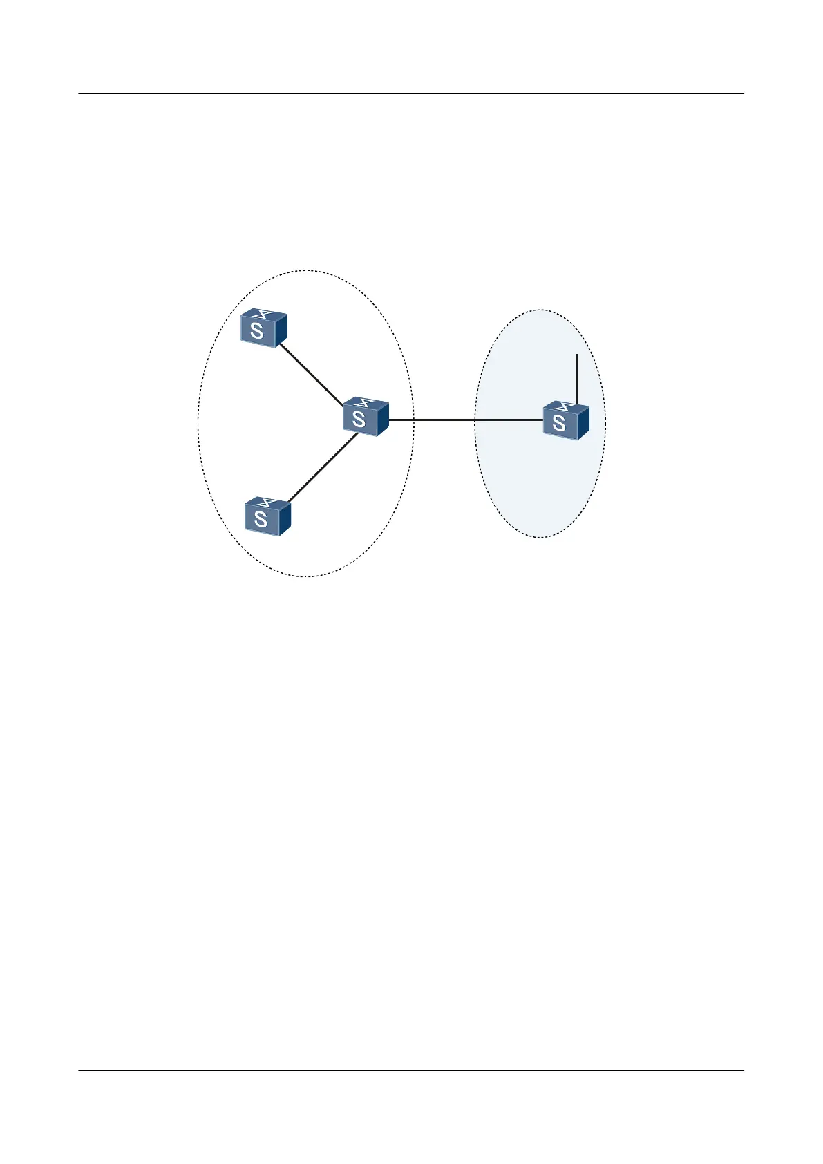
l Switch A, Switch B, Switch C, and Switch D belong to the same AS. They are
interconnected through IS-IS in the IPv6 network.
l Switch A, Switch B, and Switch C belong to area 10. Switch D belongs to area 20.
l Switch A and Switch B are Level-1 routers. Switch C is a Level-1-2 router. Switch D is a
Level-2 router.
Figure 6-10 Networking diagram of basic IS-IS IPv6 feature
SwitchA
L1
XGE0/0/1
10:1::2/64
XGE0/0/1
10:1::1/64
XGE0/0/2
10:2::1/64
XGE0/0/1
10:2::2/64
SwitchB
L1
IS-IS
Area10
IS-IS
Area20
SwitchC
L1/L2
SwitchD
L2
XGE0/0/2
20::1/64
XGE0/0/3
30::1/64
XGE0/0/1
30::2/64
Switch Interface VLANIF interface IP address
SwitchA XGigabitEthernet0/0/1 VLANIF 10 10:1::2/64
SwitchB XGigabitEthernet0/0/1 VLANIF 20 10:2::2/64
SwitchC XGigabitEthernet0/0/1 VLANIF 10 10:1::1/64
SwitchC XGigabitEthernet0/0/2 VLANIF 20 10:2::1/64
SwitchC XGigabitEthernet0/0/3 VLANIF 30 30::1/64
SwitchD XGigabitEthernet0/0/1 VLANIF 30 30::2/64
SwitchD XGigabitEthernet0/0/2 VLANIF 40 20::1/64
Configuration Roadmap
The configuration roadmap is as follows:
1. Enable the capability of IPv6 forwarding on each switch.
2. Configure an IPv6 address for each interface.
3. Enable IS-IS on each switch.
4. Configure the level.
5. Specify the network entity.
S6700 Series Ethernet Switches
Configuration Guide - IP Routing 6 IS-IS Configuration
Issue 01 (2012-03-15) Huawei Proprietary and Confidential
Copyright © Huawei Technologies Co., Ltd.
354
 Loading...