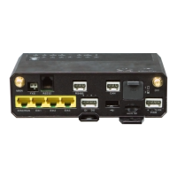
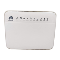
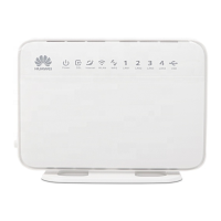
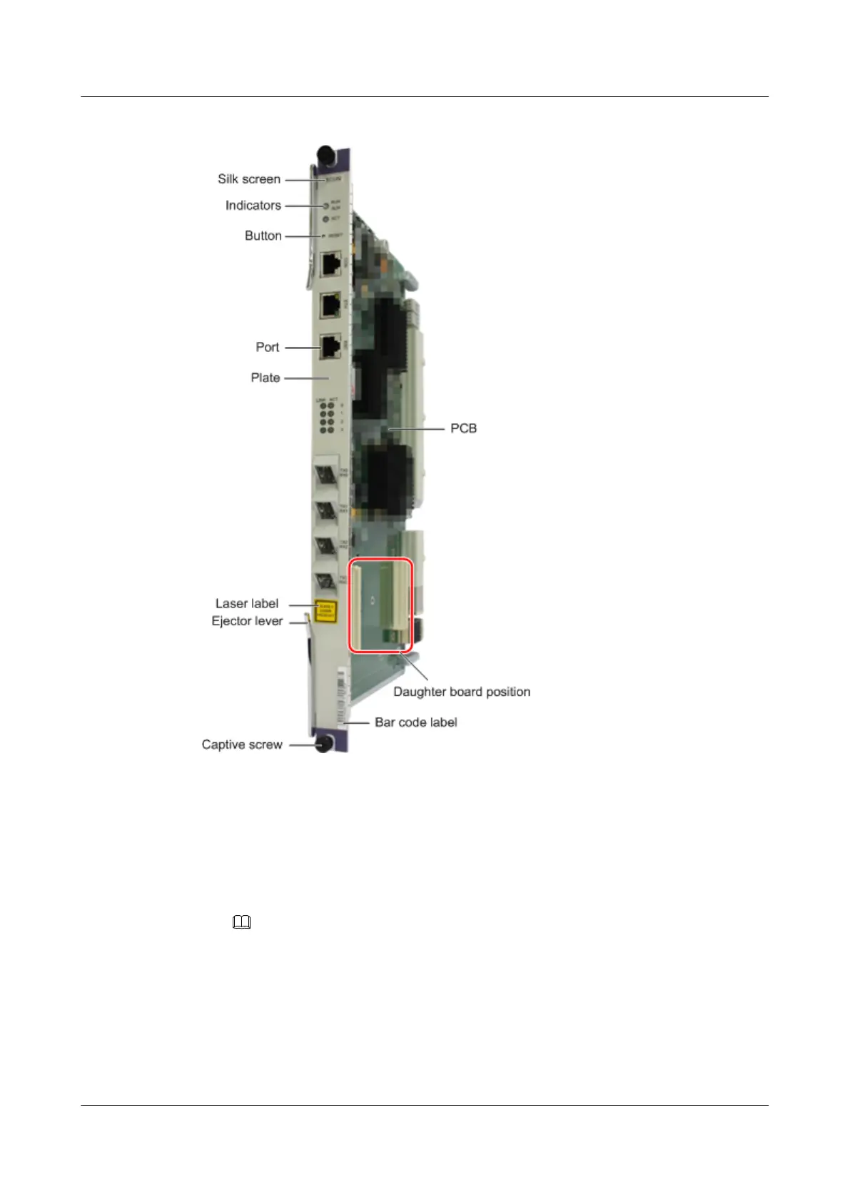
Figure 3-1 Board structure
A board mainly consists of the following parts:
l PCB
The PCB houses various functional chips of the board and is the most important part of
the board. Through the front panel, the PCB provides indicators, buttons, and ports. For
some boards, the PCB also provides a position for installing a daughter board.
NOTE
Different boards provide different indicators, buttons, and ports; not all boards support a daughter
board. For details, see the description of each board.
l Front panel, including the captive screws, ejector levers, and plate
– Captive screws: secure the board in the subrack.
– Ejector levers: used for inserting or removing the board.
– Plate: connects the PCB and the ejector levers. The plate also provides a surface for
attaching some labels (such as the bar code label and laser label).
SmartAX MA5600T/MA5603T/MA5608T Multi-service
Access Module
Hardware Description
3 Board
Issue 24 (2018-07-30) Huawei Proprietary and Confidential
Copyright © Huawei Technologies Co., Ltd.
144
 Loading...