Indicato
r
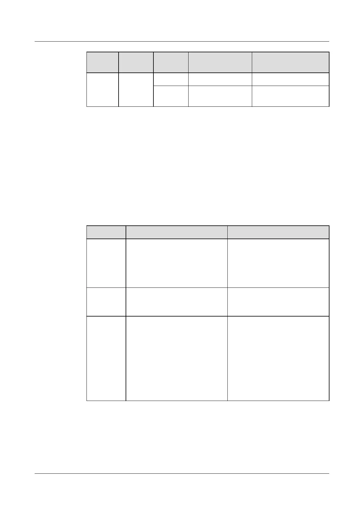
Name Color Status Meaning
ACT Data status
indicator
Yellow Blinking Data is being transmitted
- Off No data is being
transmitted
3.9 Universal Interface Board (GPIO)
Universal interface boards (installed in the GPIO slot) receive the clock signals and ESC
parameters. GPIO is short for general purpose input/output.
3.9.1 GPIO Boards Comparison
In the table, "Yes" indicates "supported" and "No" indicates "not supported".
Table 3-20 Major differences between universal interface boards
Board
BITS Clock ESC
H801BIUA
l Supports two inputs of 2 Mbit/s
or 2 MHz BITS clock signals.
l Supports one output of 2 Mbit/s
or 2 MHz clock signals.
l Provides E1 clock ports.
No
H801CITA No Provides an ESC port for receiving
and reporting the ESC alarm
information to the control board.
H801CITD
l Supports two inputs of 2 Mbit/s
or 2 MHz BITS clock signals.
l Supports two inputs of 1 PPS
+TOD time signals.
l Supports one output of 2 Mbit/s
or 2 MHz clock signals.
l Supports one output of 1 PPS
+TOD time signals.
l Provides RJ45 clock ports.
Provides seven inputs of alarm
digital parameters and one output of
alarm digital parameters.
3.9.2 H801BIUA Board Description
The H801BIUA board is a BITS interface Unit board, providing BITS input and output
functions.
SmartAX MA5600T/MA5603T/MA5608T Multi-service
Access Module
Hardware Description
3 Board
Issue 24 (2018-07-30) Huawei Proprietary and Confidential
Copyright © Huawei Technologies Co., Ltd.
296
 Loading...