8018653 1.1 Installing BSC hardware • 2-21
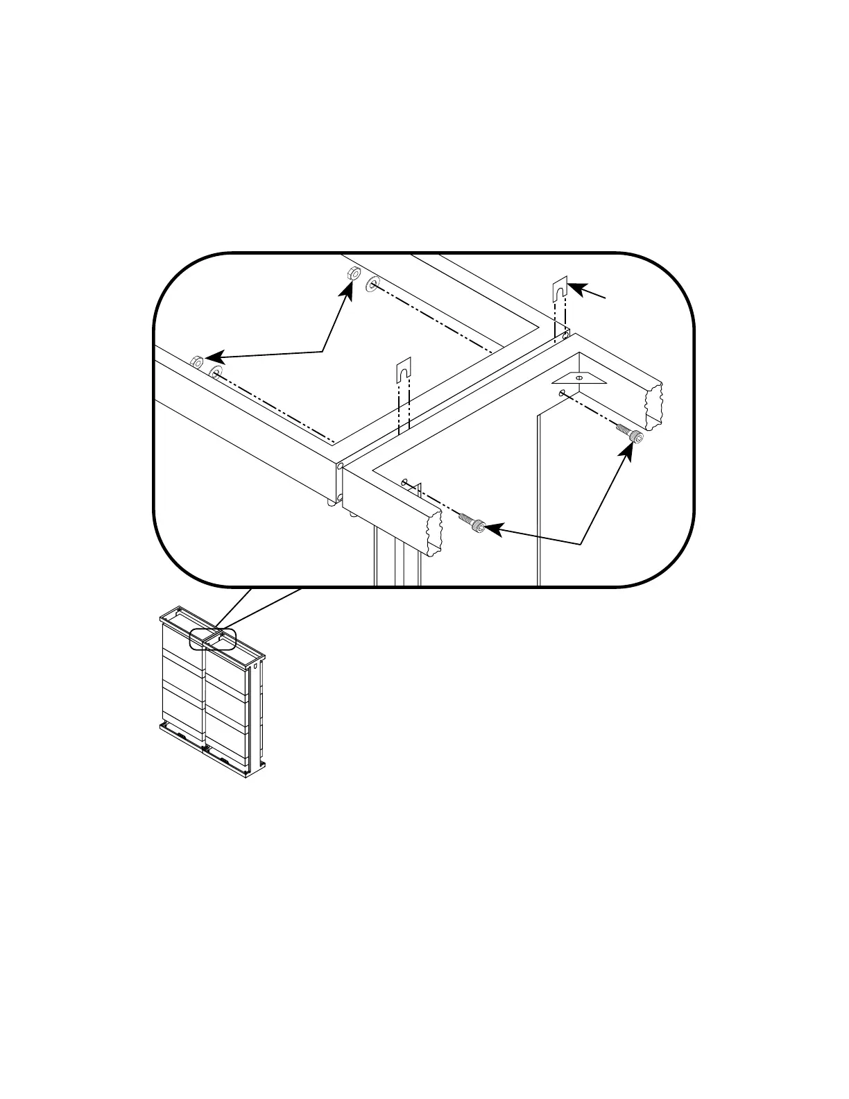
2. Install an M10 washer and hex nut onto the mounting screws
(see figure 2-13). Hand-tighten the mounting hardware.
3. Insert spacers between the rack frames so that the slots in the
spacers fit over the screw shafts (see figure 2-13).
4. Insert a contact angle between the rack frames (see figure 2-13).
MOUNTING
HARDWARE
9007016-0013
9004651-0258
MOUNTING
HARDWARE
9007034-0005
SPACER
9007016-0017
(2 PLACES)
Figure 2-14. Connecting the top frames of the BSC racks together
5. Install two 10 X 100 hex-head mounting screws through the top
side frames of the first pair of BSC racks, as shown in
figure 2-14.
 Loading...