8018653 1.1 Installing BSC hardware • 2-49
Refer to section “Commissioning” in the GMH 2000 Local Maintenance
Terminal (LMT) Operator’s Reference Manual (document 8019007) for
information on commissioning the BSC. Then continue on to
section 2.10, “Assigning BSC chassis identification codes” in this
document.
2.11
Assigning BSC chassis
identification codes
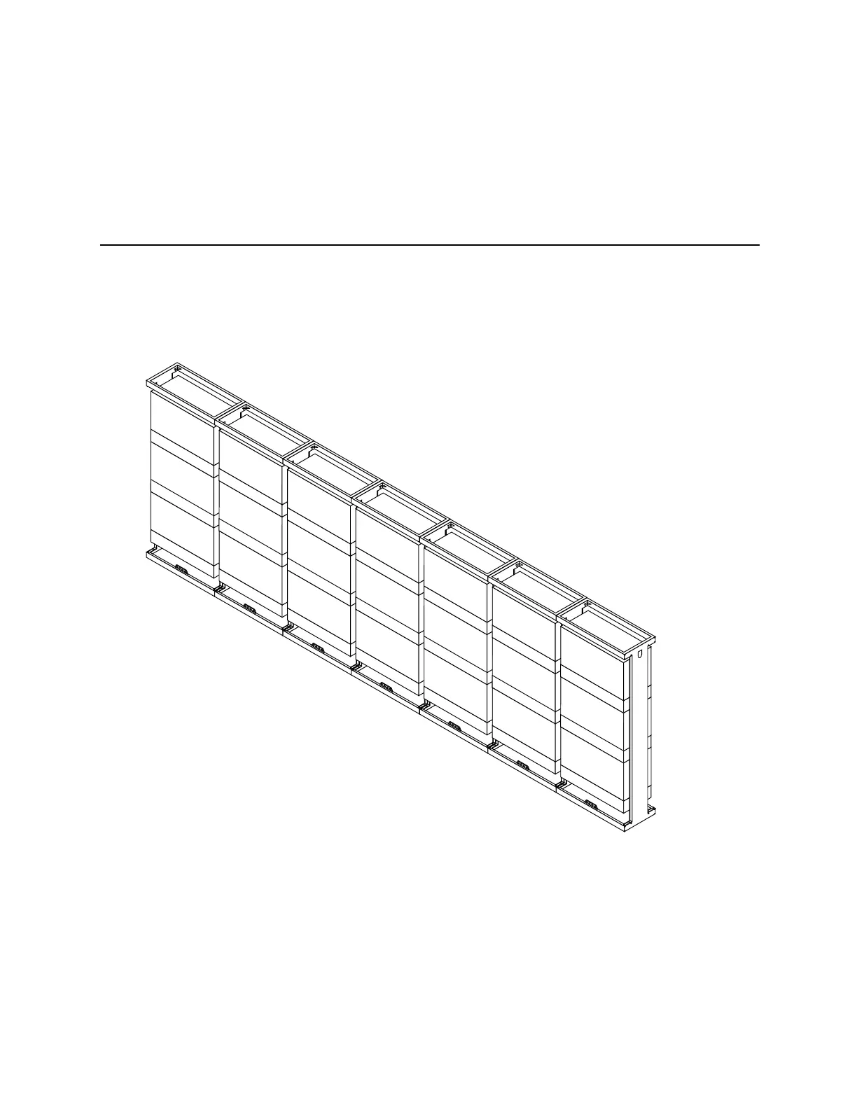
BSC racks are numbered starting from the initial BSC rack, as shown in
figure 2-31. The three BSC chassis assemblies inside each BSC rack are
numbered from the top to bottom.
FRONT OF RACKS
BSC
CHASSIS
#1
BSC
CHASSIS
#2
BSC
CHASSIS
#3
BSC RACK #1
(INITIAL RACK)
BSC
CHASSIS
#4
BSC
CHASSIS
#5
BSC
CHASSIS
#6
BSC RACK #2
(EXPANSION RACK)
BSC
CHASSIS
#7
BSC
CHASSIS
#8
BSC
CHASSIS
#9
BSC RACK #3
(EXPANSION RACK)
BSC
CHASSIS
#10
BSC
CHASSIS
#11
BSC
CHASSIS
#12
BSC RACK #4
(EXPANSION RACK)
BSC
CHASSIS
#13
BSC
CHASSIS
#14
BSC
CHASSIS
#15
BSC RACK #5
(EXPANSION RACK)
BSC
CHASSIS
#16
BSC
CHASSIS
#17
BSC
CHASSIS
#18
BSC RACK #6
(EXPANSION RACK)
BSC
CHASSIS
#19
BSC
CHASSIS
#20
BSC
CHASSIS
#21
BSC RACK #7
(EXPANSION RACK)
Figure 2-31. Numbering BSC racks and BSC chassis assemblies