8018653 1.1 Maintenance • 5-5
Replacing BSC circuit
modules
If you isolate a problem to an STM, CPM, E1, or T1 circuit module (see
figure 5-1 for locations), the entire module must be replaced as follows:
Caution
Wear an electrostatic discharge (ESD) wrist strap at
all times while handling BSC circuit modules.
Connect the wrist strap alligator clip to an unpainted
metal surface on the BSC rack or one of the BSC
chassis frames.
1. Open the front BSC rack doors.
2. Using a crosstip screwdriver, loosen the top and bottom captive
screws on the malfunctioning circuit module until the module is
no longer attached to the BSC chassis assembly.
Caution
To avoid damaging the card portion of a circuit
module, hold only the module’s metal frame.
3. Fully extend the top and bottom ejector/injector handles so that
the module is disconnected from the chassis assembly back-
plane. When that happens, slide the circuit module out of the
chassis and place the module in an ESD-protective container.
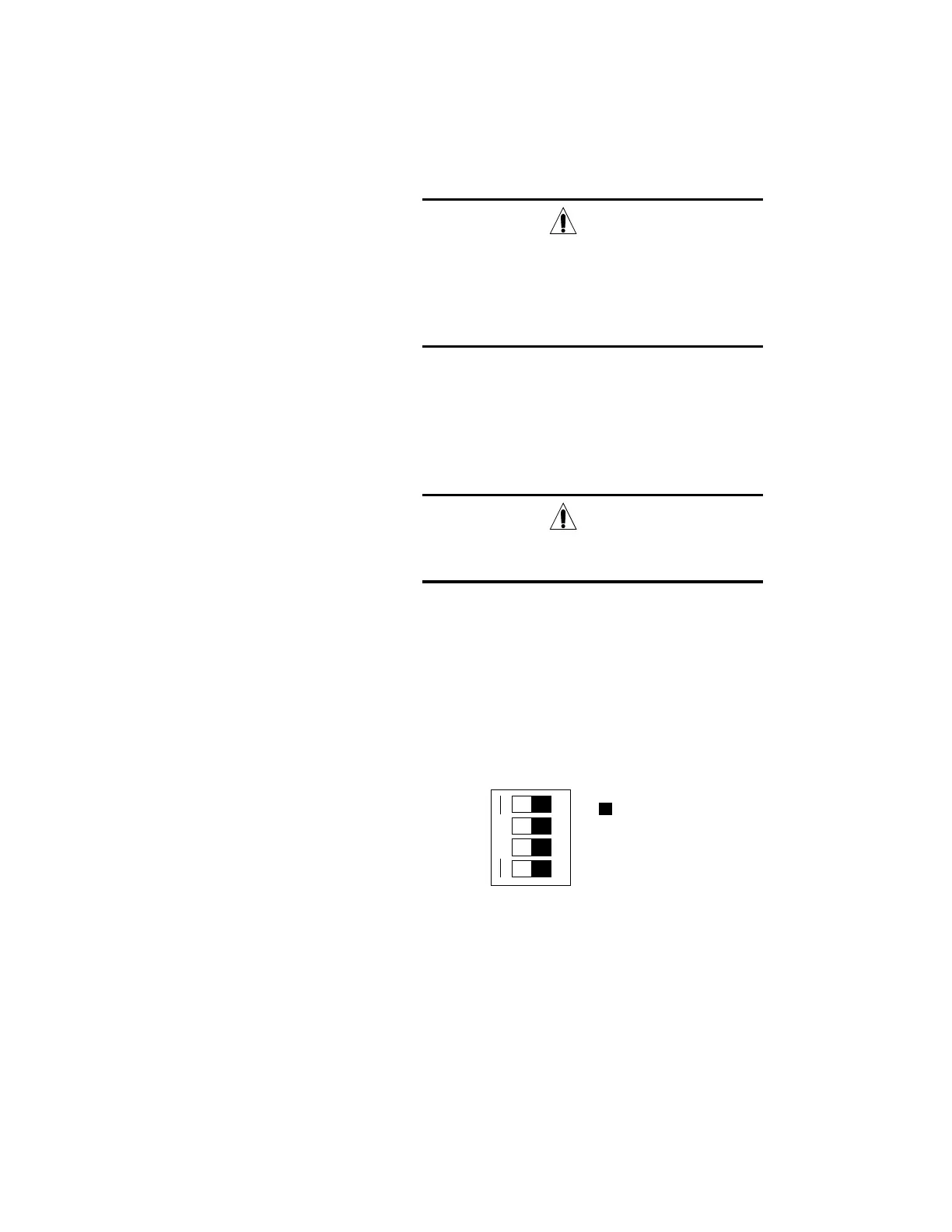
4. Verify that the replacement circuit module’s front panel dual
inline package (DIP) switches are set to the startup diagnostics
(SUDs) setting shown in figure 5-2.
Black square
indicates side of
switch that is
pressed inwards
OPEN
4321
Figure 5-2. Front panel DIP switches setting for SUDs
5. Press the front panel reset switch toggle down until it remains in
the down position.
 Loading...