8018653 1.1 Installing BSC hardware • 2-41
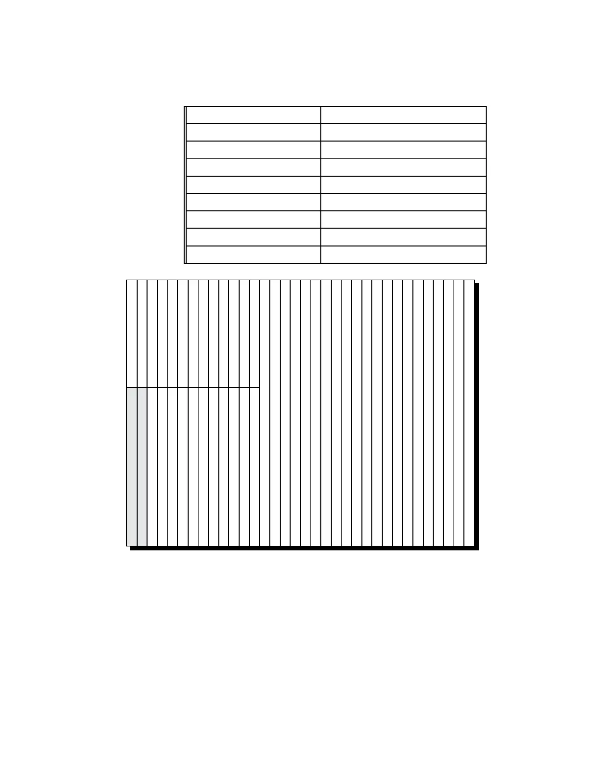
Table 2-7. BSC chassis assembly slot designations
BSC Slot Number Module type
1 through 7 top T1 interface modules
8 top Either a T1 or an E1 interface module
9 through 13 top E1 interface modules
1 and 2 bottom Reserved for future expansion
3 and 4 bottom CPM GRP configuration
5 through 8 bottom CPM CCP configuration
9 through 13 bottom CPM CAP configuration
14 through 34 STM
SLOT 1 (TOP): T1
SLOT 2 (TOP): T1
SLOT 3 (TOP): T1
SLOT 4 (TOP): T1
SLOT 5 (TOP): T1
SLOT 6 (TOP): T1
SLOT 7 (TOP): T1
SLOT 8 (TOP): T1 or E1
SLOT 9 (TOP): E1
SLOT 10 (TOP): E1
SLOT 11 (TOP): E1
SLOT 12 (TOP): E1
SLOT 13 (TOP): E1
SLOT 14: STM
SLOT 15: STM
SLOT 16: STM
SLOT 17: STM
SLOT 18: STM
SLOT 19: STM
SLOT 20: STM
SLOT 21: STM
SLOT 22: STM
SLOT 23: STM
SLOT 24: STM
SLOT 25: STM
SLOT 26: STM
SLOT 27: STM
SLOT 28: STM
SLOT 29: STM
SLOT 30: STM
SLOT 31: STM
SLOT 32: STM
SLOT 33: STM
SLOT 34: STM
SLOT 1 (BOTTOM): RESERVED
SLOT 2 (BOTTOM): RESERVED
SLOT 3 (BOTTOM): GRP
SLOT 4 (BOTTOM): GRP
SLOT 5 (BOTTOM): CCP
SLOT 6 (BOTTOM): CCP
SLOT 7 (BOTTOM): CCP
SLOT 8 (BOTTOM): CCP
SLOT 9 (BOTTOM): CAP
SLOT 10 (BOTTOM): CAP
SLOT 11 (BOTTOM): CAP
SLOT 12 (BOTTOM): CAP
SLOT 13 (BOTTOM): CAP
Figure 2-26. BSC chassis assembly circuit module slot designations
 Loading...