5-6 • Maintenance 8018653 1.1
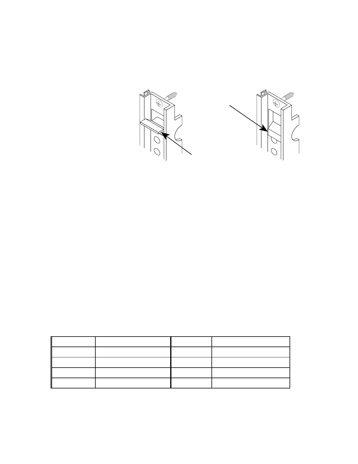
6. Insert the replacement circuit module into the same slot of the
BSC chassis assembly from which the defective module was
removed. Extend the upper and lower ejector/injectors as shown
in figure 5-3.
EJECTOR/INJECTOR
EXTENDED
EJECTOR/INJECTOR
CLOSED
Figure 5-3. Ejector/injector operation
6. Slide the module into the slot until it makes contact with the
backplane. When that happens, close both ejector/injectors to
seat the module into the backplane.
7. Use a crosstip screwdriver to tighten the T1 module’s top and
bottom captive screws.
6. Release the front panel reset switch toggle so that it returns to
the center position. Verify that, after approximately 15 seconds,
the module’s status LED readout displays one of the codes
listed in table 5-1.
9. Close the front rack doors.
The circuit module is operational; verify proper operation with the base
station control console (BCC) operator, then refer to section 5.5,
“Standard HNS return and repair procedure” for information on returning
the defective module to HNS for repair.
Table 5-1. BSC circuit module status LED readouts
Display Code Description Display Code Description
I Switched In, In Service i Switched Out, In Service
O Switched In, Out Of Service o Switched Out, Out Of Service
A Switched In, Maintainance a Switched Out, Maintainance
C Switched In, Camp On c Switched Out, Camp On
 Loading...