8018653 1.1 Installing BSC hardware • 2-27
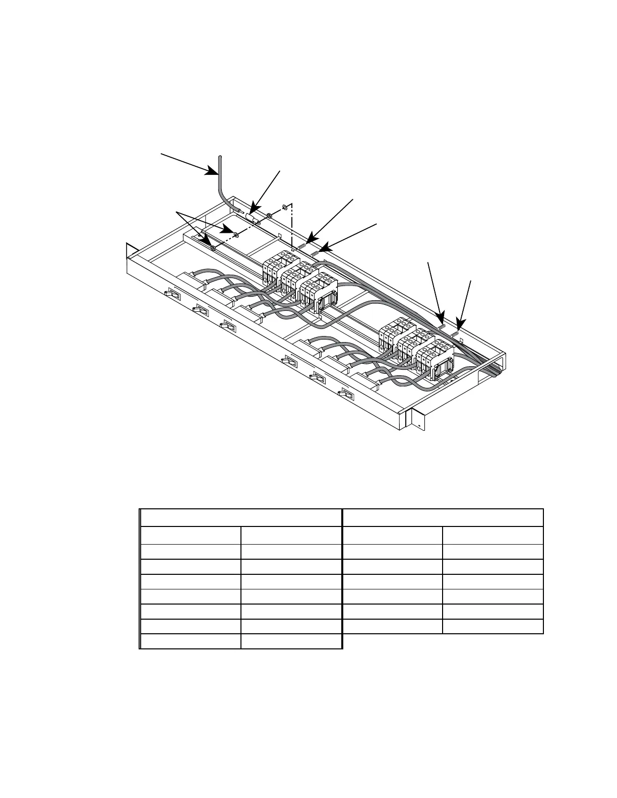
6. Use a 9/16-inch (or metric equivalent) wrench to install safety
ground cable E1 (GND) and 9/16-inch mounting hardware onto
PDU grounding stud E1 (see figure 2-19 for locations).
CHASSIS 1
CIRCUIT B
CHASSIS 2
CHASSIS 3
CHASSIS 1
CIRCUIT A
CHASSIS 2
CHASSIS 3
GROUNDING
STUD E1
GROUNDING
STUD E2
GROUNDING
STUD E3
GROUNDING
STUD E4
GROUNDING STUD
HARDWARE
SAFETY GROUND
CABLE
TERMINAL LUG
9006945-0002
(FROM INSTALLATION KIT)
Figure 2-19. Grounding the BSC rack
7. Repeat steps 3 and 4 to install the cables listed in table 2-5.
Table 2-5. Input power cable connections
PDU Circuit A PDU Circuit B
Cable Destination Cable Destination
TB1-1 (-48V) TB1-1 TB4-1 (-48V) TB4-1
TB1-2 (RTN) TB1-2 TB4-2 (RTN) TB4-2
E1 (GND) E1 TB5-1 (-48V) TB5-1
TB2-1 (-48V) TB1-1 TB5-2 (RTN) TB5-2
TB2-2 (RTN) TB1-2 TB6-1 (-48V) TB6-1
TB3-1 (-48V) TB1-1 TB6-2 (RTN) TB6-2
TB3-2 (RTN) TB1-2
 Loading...