8018653 1.1 Installing BSC hardware • 2-37
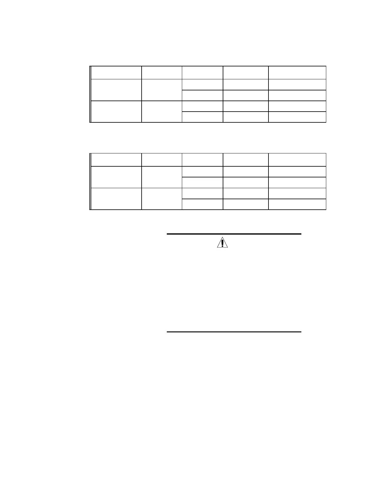
Table 2-6. Trunk cable J79, T1 RVS listing by cable connector pin number (Cont.)
Trunk
Number
Module
Slot/Port
Backplane
Signal Name
Backplane
Conn#.Pin#
Wire Color Code
Solid/Stripe
Future Expansion 8/0 RVS RING 14 J79.24 Black/Orange
T1-14 RVS TIP 14 J79.25 Orange/Black
Future Expansion 8/1 RVS RING 15 J79.22 Black/Blue
T1-15 RVS TIP 15 J79.23 Blue/Black
Table 2-6. Trunk cable J80, T1 FWD listing by cable connector pin number (Cont.)
Trunk
Number
Module
Slot/Port
Backplane
Signal Name
Backplane
Conn#.Pin#
Wire Color Code
Solid/Stripe
Future Expansion 8/0 FWD RING 14 J80.24 Black/Orange
T1-14 FWD TIP 14 J80.25 Orange/Black
Future Expansion 8/1 FWD RING 15 J80.22 Black/Blue
T1-15 FWD TIP 15 J80.23 Blue/Black
Caution
Bear in mind while routing BSC E1/T1 interface
cables that there is not much clearance between the
back of the BSC chassis and the rear rack doors. The
cables must be routed in such a way that the doors
will close easily, otherwise the cable could be
damaged. Route the E1/T1 cables along the top of
each backplane shield as shown in figure 2-24. Use
cable ties to secure the cables to the cable posts
positioned along both sides of the BSC chassis (see
figure 2-24).
 Loading...