8018653 1.1 Installing BSC hardware • 2-43
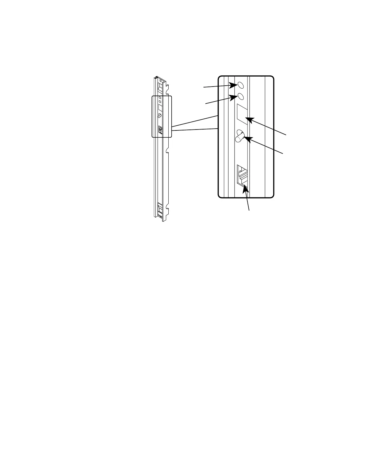
3. Press the front panel reset switch toggle down until it remains in
the down position (see figure 2-28 for locations).
OK
ALM
DEBUG
S
T
A
T
U
S
RESET
DEBUG PORT
RESET
SWITCH
STATUS
LED READOUT
OK
LAMP
ALM
LAMP
Figure 2-28. Module front panel
4. Slide the module into the slot until it makes contact with the
backplane. When that happens, close both ejector/injectors to
seat the module into the backplane.
5. Use a crosstip screwdriver to tighten the T1 module’s top and
bottom captive screws.
6. Release the front panel reset switch toggle so that it returns to
the center position. Verify that the status light-emitting diode
(LED) readout displays a u after completing startup diagnostics
(SUDs).
Note
If the status readout does not display a u, the
module has failed SUDs. Refer to section 4,
“Troubleshooting.”
Repeat steps 1 through 6 to install additional T1 modules in ascending
order into the BSC chassis, then refer to section “Installing E1 interface
modules.”
 Loading...