49
Note: If the push force is too small, a false detection of push & hold
condition may occur due to slide resistance, etc., so exercise
caution.
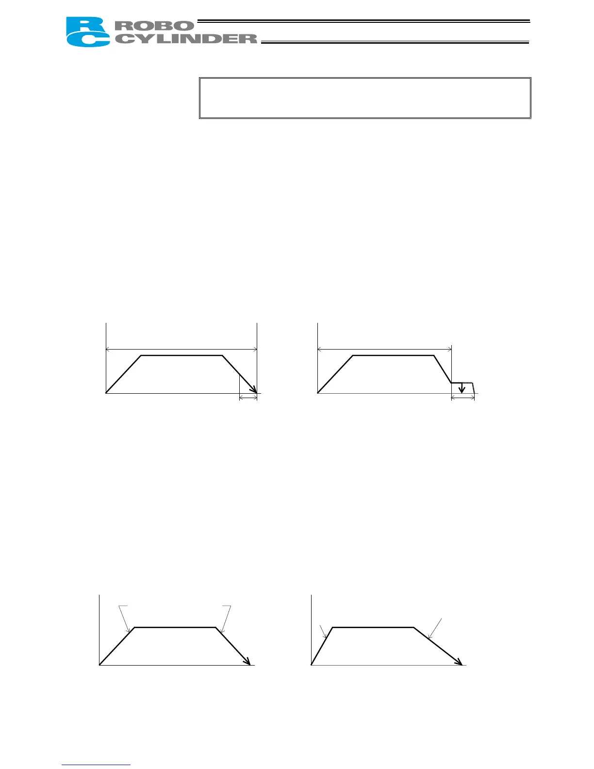
(6) Positioning band
(Pos. band)
• The function of the positioning band varies depending on whether the
push & hold setting in (5) is “0” or “other than 0.”
(A) Push = 0 (Positioning mode)
• In the positioning mode, enter the position-complete detection width
(distance to the target position), in [mm].
• The distance to the target position indicates the range prior to the target
position, upon entry of the actuator in which range a position complete
signal will be output.
The default value is “0.1 [mm]” (Fig. A).
(B) Push = Other than 0 (Push & hold mode)
• Enter the maximum push amount (distance from the target) in the push
& hold mode, in [mm] (Fig. B).
• If the push direction corresponds to the negative direction along the
displayed coordinate axis, add a – (minus) sign to the entered value.
Fig. A Fig. B
(7) Acceleration only MAX
(ACC MAX)
• Select the specified acceleration or maximum acceleration by entering
“0” or “1.”
The default value is “0.”
0: Specified acceleration --- The value entered in (4) becomes the
actual acceleration/deceleration.
1: Maximum acceleration --- The maximum acceleration.
The deceleration conforms to the value
entered in (4).
Speed
Speed
(5) Push = 0
Distance to the position set in (2)
(5) Push = Other than 0
Distance to the position set in (2)
Moving distance
Moving distance
(6) Positioning band (6) Positioning band
(7) Acceleration only MAX = 0 (7) Acceleration only MAX = 1
Acceleration/deceleration
set in (4)
cceleration/deceleration
set in (4)
Maximum acceleration
Speed
Speed
Moving distance
Moving distance

 Loading...


