3. Operation
Fieldbus Communication
96
RCP6
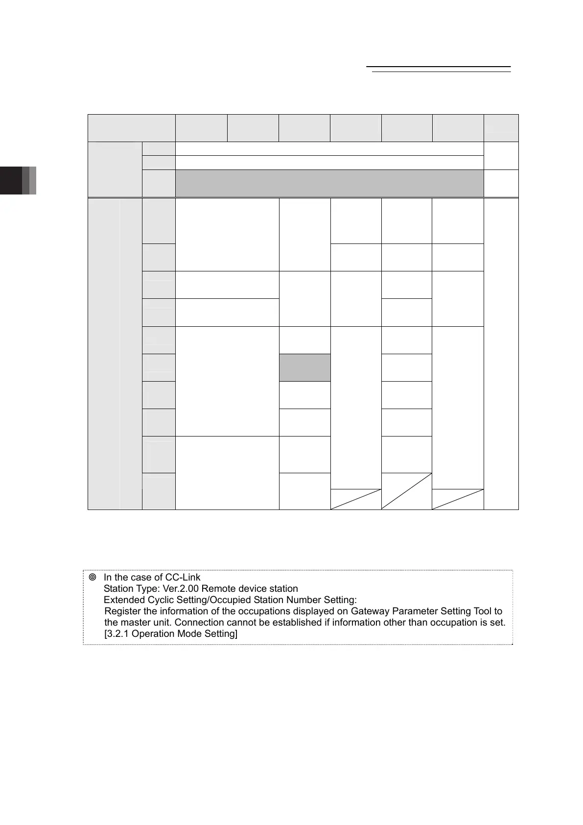
y RCP6S GW Output → PLC Input (n is PLC input top word address from RCP6S GW)
(Note 1)
PLC
Input Area
Simple Direct
Mode
Positioner 1
Mode
Direct
Indication
Mode
Positioner 2
Mode
Positioner 3
Mode
Positioner 5
Mode Details
n Gateway Status 0
n+1 Gateway Status 1
3.4.2
RCP6S
Gateway
Response
Area
n+2
to
n+7
Occupied Areas
(Note 2)
-
n+8
Completed
Position No./
Simple
Alarm ID
(Axis No.0)
Status
Signal/
Completed
Position
(Axis No.0)
Completed
Position No./
Simple Alarm
ID (Axis
No.0)
n+9
Current Position
(Axis No.0)
Current
Position
(Axis No.0)
Status
Signal
(Axis No.0)
Assignment
Area for
Axis No.1
Status Signal
(Axis No.0)
n+10
Completed Position No./
Simple Alarm ID
(Axis No.0)
Assignment
Area for
Axis No.2
n+11
Status Signal
(Axis No.0)
Command
Current
(Axis No.0)
Assignment
Area for
Axis No.1
Assignment
Area for
Axis No.3
Assignment
Area for
Axis No.1
n+12
Current
Speed
(Axis No.0)
Assignment
Area for
Axis No.4
n+13
Occupied
Area
(axis No.0)
Assignment
Area for
Axis No.5
n+14
Alarm Code
(Axis No.0)
Assignment
Area for
Axis No.6
n+15
Assignment
Area for
Axis No.1
Status Signal
(Axis No.0)
Assignment
Area for
Axis No.7
n+16
to
n+23
Assignment
Area for
Axis No.1
Assignment
Area for
Axis No.8
to No.15
Assignment
Area for
Axis No.2
to No.15
(~n+39)
Assignment
Area for
Axis No.2
to No.15
(~n+39)
Connected Axes Response Area
n+24
to
n+71
Assignment
Area for
Axis No.2
to No.15
Assignment
Area for
Axis No.2
to No.7
(Note 3)
3.4.3
to
3.4.8
Note 1 For CC-Link, n and n+1 are for input and output bit addresses, and n+8 is for the top address of data
register.
Note 2 This is the domain occupied unconditionally. Therefore, this domain cannot be used for any other
purpose.
Note 3 For CC-Link, assignment is available up to Axis No. 15 (~n+135).
In the case of CC-Link
Station Type: Ver.2.00 Remote device station
Extended Cyclic Setting/Occupied Station Number Setting:
Register the information of the occupations displayed on Gateway Parameter Setting Tool to
the master unit. Connection cannot be established if information other than occupation is set.
[3.2.1 Operation Mode Setting]
The domain of the axis not connected is to be an unoccupied domain when the left-justification
setting feature is not to be used.
The domain of the axis number set for the left-justification will be justified to the left when the
left-justification setting feature is to be used.
Refer to “3.1.2 Relation between Axis Number and PLC Address Domain (Left-Justification
Feature)” for the left-justification setting feature.
3.4.1

 Loading...