2. Wiring
Fieldbus Communication
64
RCP6
2.3.6 Wiring of Fieldbus Connector
Refer to the instruction manuals of the each fieldbus master unit and mounted PLC for details.
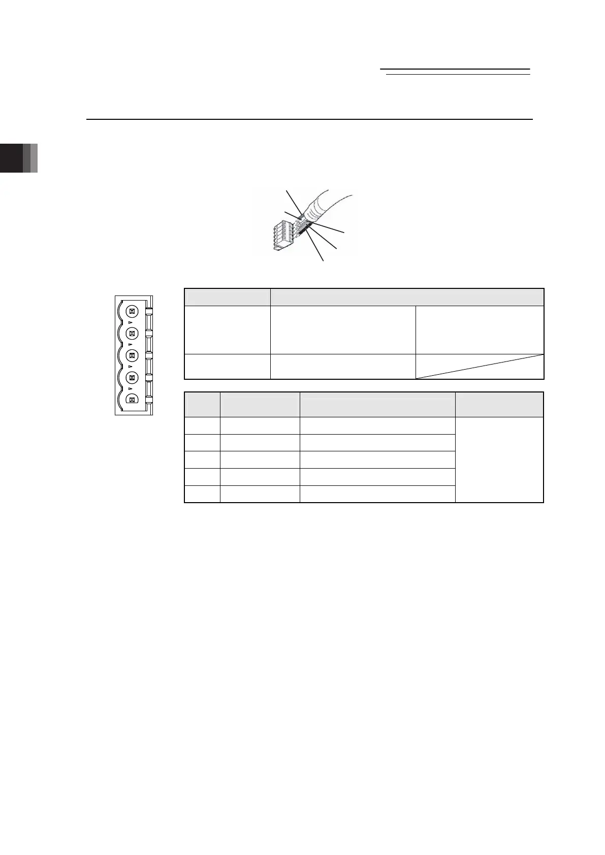
1) DeviceNet Type
Shield
BL (CAN L)
RD (V+)
WT (CAN H)
BK (V
-
)
Connector Name DeviceNet Connector
Cable Side MSTB2.5/5-STF-5.08 AU M
Enclosed in standard
package
Manufactured by
PHOENIX CONTACT
Gateway Unit
Side
MSTB2.5/5-GF-5.08 AU
Pin
No.
Signal Name
(Color)
Description
Applicable Cable
Diameter
1
V- (Black) Power Supply Cable - Side
2 CAN L (Blue) Communication Data Low Side
3 Shield (None) Shield
4 CAN H (White) Communication Data High Side
5 V+ (Red) Power Supply Cable + Side
Dedicated cable
for DeviceNet
(Note) Connect a terminal resistor (121Ω) between CAN L and CAN H if the
unit comes to the end of the network. [Refer to 2.2 [5] Wiring Layout for
Fieldbus.]
1
2
3
4
5
Front view of
connector on
gateway unit side

 Loading...