10. Appendix
Fieldbus Communication
RCP6
Note 1 The contents recorded in the teaching tool and Modbus communication can be checked.
To check in the teaching tool [Refer in each instruction manual for details]
x
TB-01/TB-02 [Monitor] → [Maintenance]
x
TB-02 [Information] → [Maintenance Information]
x
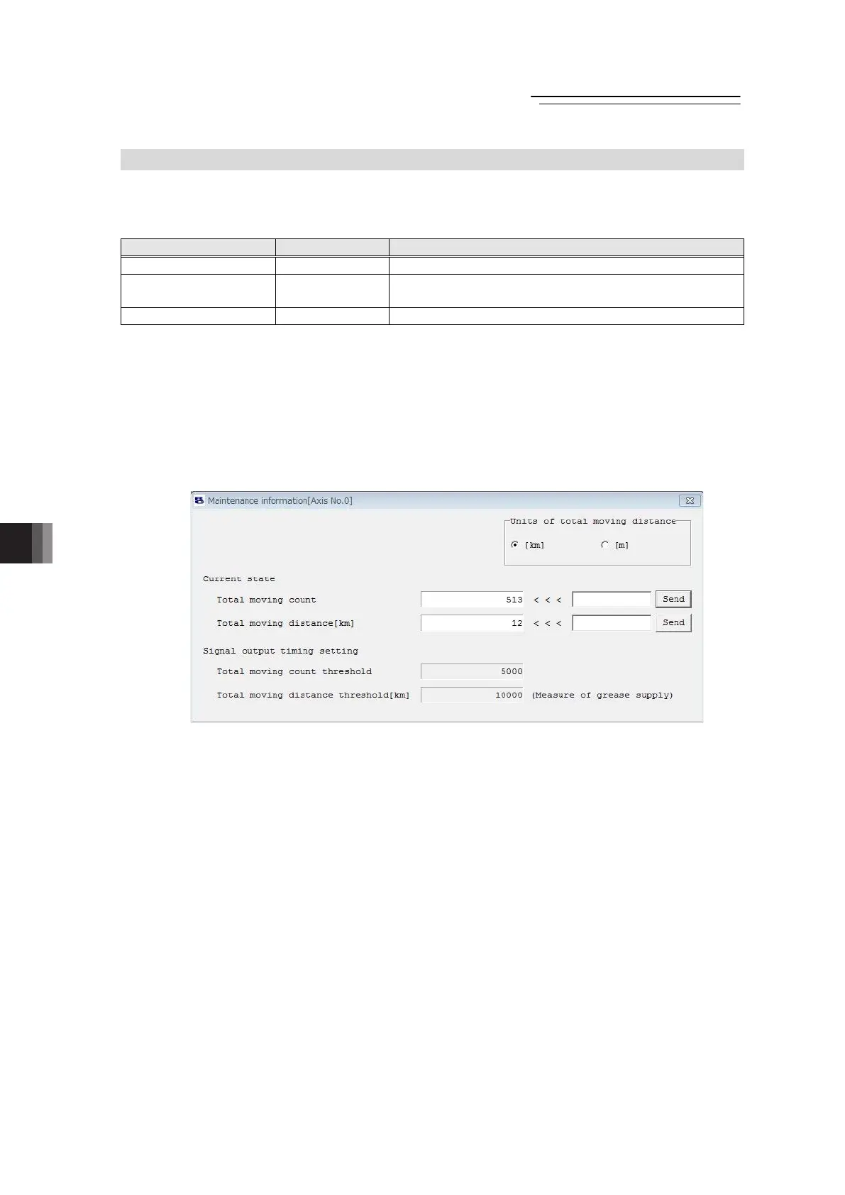
RC PC software [Monitor (M)] → [Maintenance Information (I)] → Select axis
Note 2 Set in Parameter No. 147 “Total Times of Movement Target” and No. 148 “Total Drive
Distance Target”. [Refer to 8.2 [60] and [61].]
Note 3 The message level alarms “04E Times of Movement Target Exceeded” and “04F Drive
Distance Target Exceeded” are output. [Refer to 9.4.3 Alarm Codes on Driver Board (Each
Axis)]
Note 4 It outputs a light error alarm (ALML). [Refer to 3.71. [21] and 8.2 [62].]

 Loading...