2. Wiring
Fieldbus Communication
57
RCP6
2.3 Wiring Method (Gateway Unit)
2.3.1 Wiring to Power Input Connector
The power cables of the gateway unit are to be connected to the motor power supply connector
and the control power supply connector on the main body.
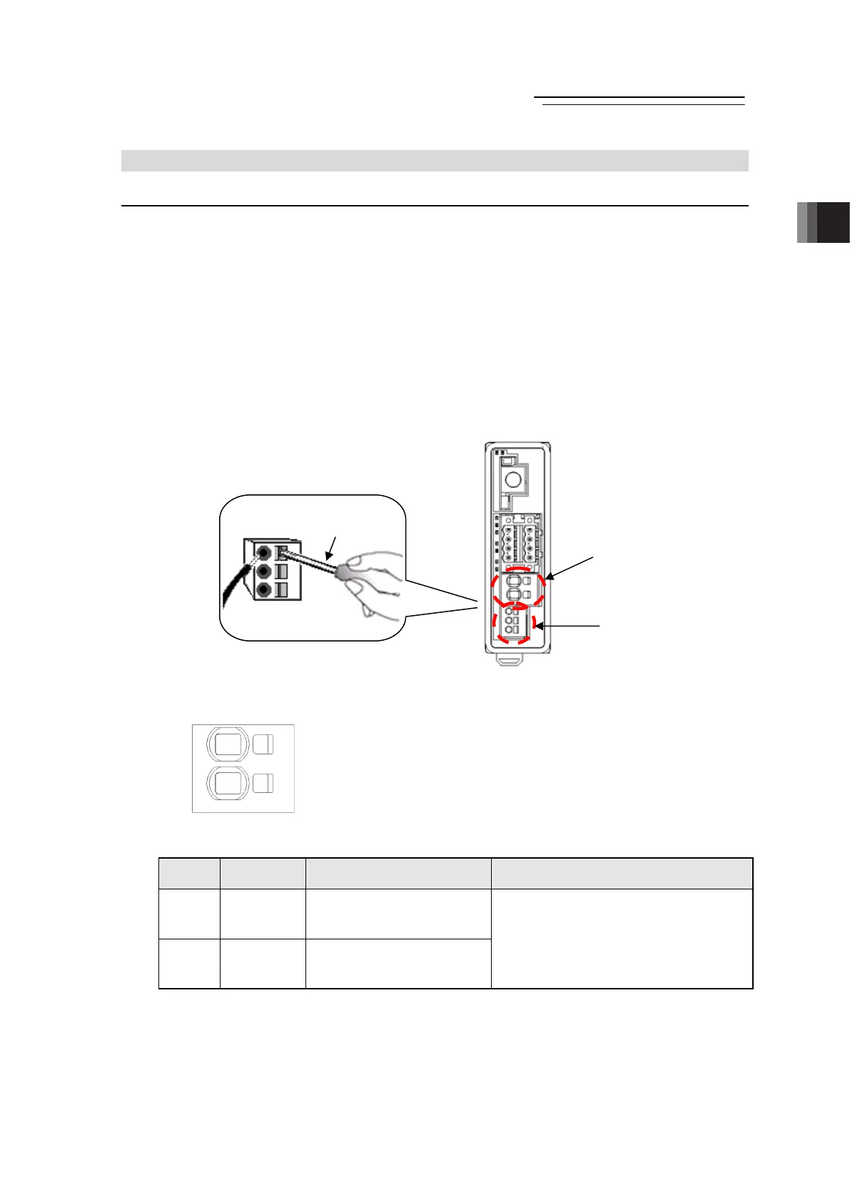
Strip the sheath of the applicable wires for 10mm and insert them to the connector.
[How to Insert]
1. Put a small slotted screwdriver in the opening on the right of the inlet deeply till it hits the end.
2. Open the inlet completely and put in the stripped end of the electric wires.
3. Pull out the slotted screwdriver to hold the wires.
4. Pull back the fixed wires to make sure that they are held tightly.
Note Put in a slotted screwdriver till it hits the end, otherwise it could be difficult to hold the
electric wires or the wires could be easy to pull out. Pay attention to this difference.
Gateway Unit
[1] Motor Power Supply Connector
Connector model: SPT5/2-H-7.5-ZB (Manufactured by PHOENIX CONTACT)
(Note) If supplying power with using a 24V DC, having it turned ON/OFF, keep the 0V connected and have the +24V
supplied/cut (cut one side only).
Pin No. Signal Name Description Applicable cable diameter
1 MP Motor Power Supply 24V Input
2 GND 0V Input
KIV8 to 0.5mm
2
(AWG8 to 20)
Select the cable thickness allowable for the
current figured out in the “1.3 Calculation for
Power Capacity”
(*)
.
* It is no problem to calculate the current
consumption using the rated value.
Slotted
Screwdrive
Motor Power
Supply Connector
Control Power
Supply Connector
Main body
Connector
1
2

 Loading...