3. Operation
Fieldbus Communication
78
RCP6
3.1.2 Relation between Axis Number and PLC Address Domain (Left-Justification
Feature)
There are axis numbers allocated in advance on the gateway unit slot and the hub unit slot. The
relation between the axis number and the PLC address domain differs as stated below depending
on the fieldbus I/O domain left-justification setting feature (hereafter stated as the left-justification
setting feature).
(Note) The left-justification setting is to be established in Gateway Parameter Setting Tool (Ver.
2.4.1.0 or later).
Refer to [3.2.1 Operation Mode Setting] and [3.8 Gateway Parameter setting Tool]
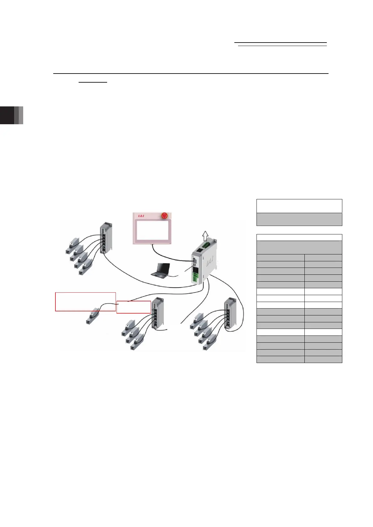
(1) When Left-Justification Setting Feature is set “Invalid”
The PLC address domain of the axis not connected is to be an unoccupied domain.
(Example for Connection) When Axis No. 5, 6, 7 and 11 are not connected;
(Note) Refer to [3.4.1 PLC Address Construction by Each Operation Mode] for details of the PLC
address domain.
Left-Justification Feature
Invalid
PLC Address Area
Gateway Unit +
Command Area
Axis No.0 area Connection
Axis No.1 area Connection
Axis No.2 area Connection
AxisNo.3 area Connection
Axis No.4 area Connection
Axis No.5 area Unoccupied
Axis No.6 area Unoccupied
Axis No.7 area Unoccupied
Axis No.8 area Connection
Axis No.9 area Connection
Axis No.10 area Connection
Axis No.11 area Unoccupied
Axis No.12 area Connection
Axis No.13 area Connection
Axis No.14 area Connection
Axis No.15 area Connection
Hub Unit 2
Hub Unit 3
Hub Unit 0
Gateway
Unit
USB
Connection
Axis No.10
Axis No.9
Axis No.8
Axis No.7 (Not Connected)
Axis No.6 (Not Connected)
Axis No.5 (Not Connected)
Axis No.4
Axis No.3
Axis No.2
Axis No.1
Axis No.0
PC
Teaching
PIO, FB
Axis No.11
(Not Connected) ×
Axis No.15
Axis No.14
Axis No.13
Axis No.12

 Loading...