3. Operation
Fieldbus Communication
130
RCP6
3.6.2 Incremental
Follow the steps below to turn ON the power to the controller.
1) Control power and the drive (24V DC).
2) Cancel the emergency stop condition or make the motor drive power supply available to turn
ON.
3) If using the servo-on signal, input the signal from the host side.
4) Input the home return signai (HOME) from the host side.
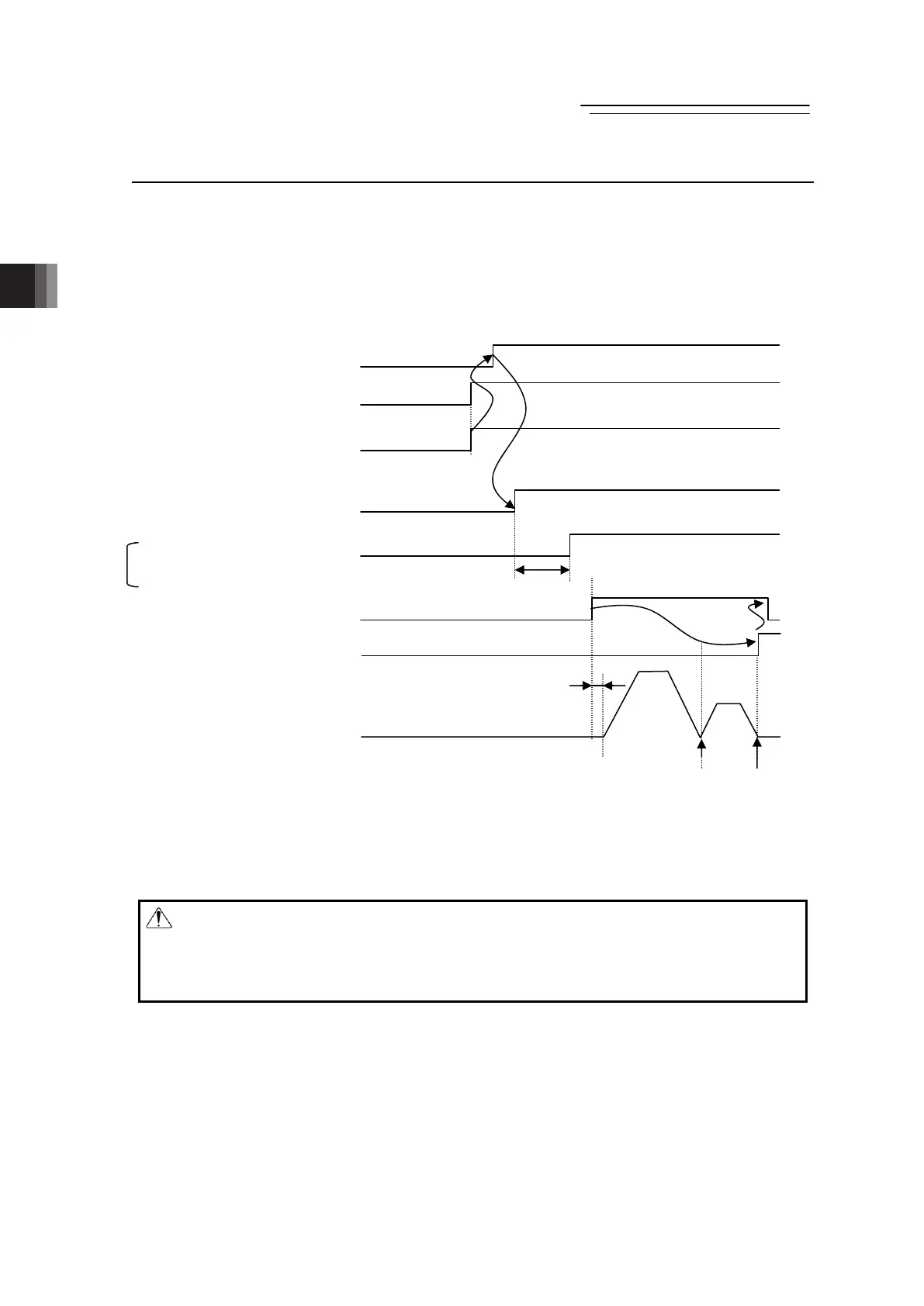
Safety Circuit Status Emergency Stop Emergency Stop Release
Control power (24V DC) input
Driving source (24V DC) input
Servo ON (SON) input
Status LEDs for Driver
Servo ON (SYS*) output
Home return signai (HOME) input
Home return completion
(HEND) output
Actuator operation
Note 1 For RCM-P6AC, have a latency of 1.6sec or more before inputting a movement
(home-return) command after the servo is turned on for the first time after the power
is booted in order to detect the magnetic pole phase. In the second time or later,
make the latency of 60ms or more.
Warning: Executing a servo ON when the actuator is position very close to a mechanical
end may cause the magnetic pole phase detection operation to malfunction and
reporting of the magnetic pole unconfirmed or excitation detection errors.
Always move the actuator physical position away from the mechanical end before
executing the servo ON command.
1.6sec or less
o
e
20ms (TYP)
Home return
Mechanical
end
Home
position

 Loading...